The Dynamic Routing Gateway (DRG) is a very powerful Customer Connectivity resource, a virtual router. It is the basic tool for connecting to on-premises or to other Cloud Service Providers via a FastConnect Virtual Circuit, or via a Site-to-Site VPN connection, and also, for connecting to remote OCI regions on your own tenancy, or to a third-party OCI tenancy.
Typically, if you are in any given region, let’s say Phoenix, and you connect a Virtual Cloud Network (VCN) in this region to your on-premises Local Area Network (LAN), you will either use a Site-to-Site VPN connection or you will use a FastConnect circuit. Both of these resources are attachments to the Dynamic Routing Gateway. And so is the VCN.
Our OCI documentation clearly highlights the DRG Attachments:
- VCN attachments: you can attach multiple VCNs to a single DRG. Each VCN can be in the same or different tenancies as the DRG.
- RPC attachments: you can peer a DRG to other DRGs (including DRGs in other regions or in other tenancies) using remote peering connections.
- IPSEC_TUNNEL attachments: you can use Site-to-site VPN to attach two or more IPsec tunnels to your DRG to connect to on-premises networks.
- VIRTUAL_CIRCUIT attachments: you can attach one or more FastConnect virtual circuits to your DRG to connect to on-premises networks.
In this post we will detail the steps needed for configuring the DRG Route Tables and Route Distributions when there is a VCN that simultaneously has a Site-to-Site VPN connection to on-premises, and a Remote Peering Connection (RPC) to another OCI region; and there is a need for extending the connection from on-premises to the remote OCI region. Setting up the VPN and RPC are not covered.
When you create a DRG, by default it comes with two Autogenerated DRG Route Tables. One of which is for VCN attachments; and another one for RPC, IPsec, and Virtual Circuits attachments. These route tables will indicate to the DRG what to do with the traffic coming in from these resources. These Route Tables obtain their routes from a Route Distribution associated with them.
The Autogenerated DRG Route Table for VCN attachments is independent of the VCN Route Table. For example, when you create a DRG, prior to attaching any resource to it, the Autogenerated DRG route Table for VCN attachments has no route rules in it. If you create a VCN with the VCN wizard, accepting the offered CIDR for the VCN and the subnets (10.0.0.0/16), and you then attach this VCN to the DRG, the Autogenerated DRG route Table for VCN attachments will now be automatically populated with the CIDR blocks of both subnets. See image 1.
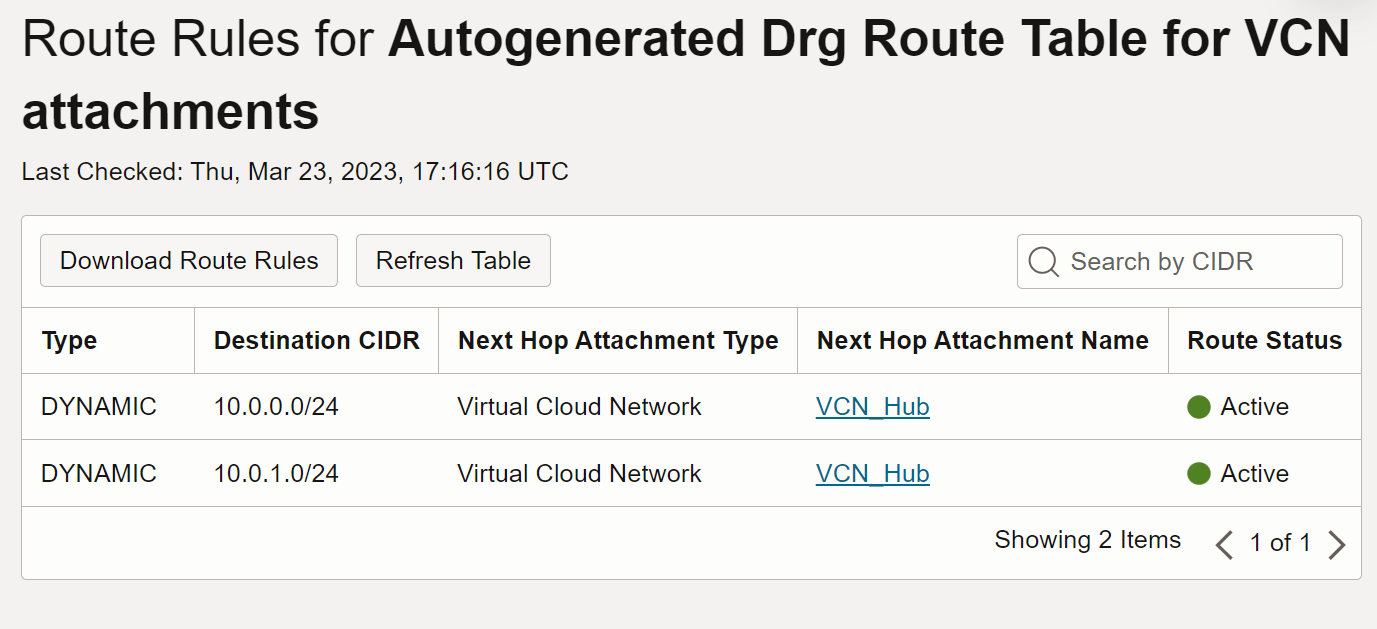
This route table is very different from the two VCN route tables that the VCN Wizard creates. The route rules in the Autogenerated DRG route Table for VCN attachments indicate that the DRG is ready for routing to the next hop, however you still need to have a route in the VCN that points to the DRG.
Continuing with our example, if you then attach an active IP Sec Tunnel to the DRG, The route rules in the Autogenerated DRG route Table for VCN attachments will automatically be populated with the route to the IPsec tunnels. See image 2.
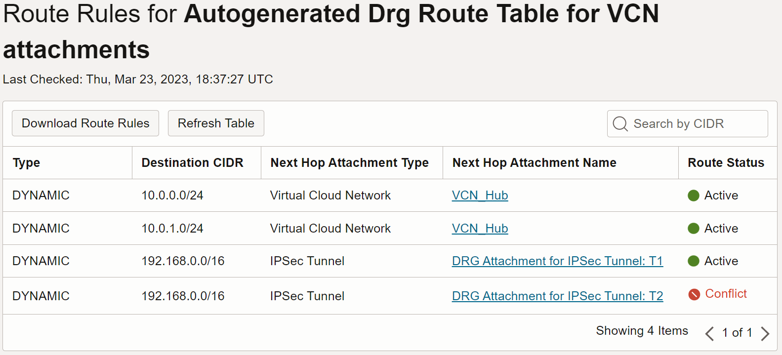
Image 2
The IPsec CIDR conflict will prevent the DRG from routing to the second tunnel. The two tunnels are created for redundancy purposes in case one goes down. The conflicted route is less preferred and will only become active if, either the primary tunnel goes down, or equal-cost multi-path routing (ECMP) is enabled. ECMP is a configuration option.
If you now also check for the Route Rules in the Autogenerated DRG Route Table for RPC, VC, and IPsec attachments you will only see the rules for VCN. See image 3.
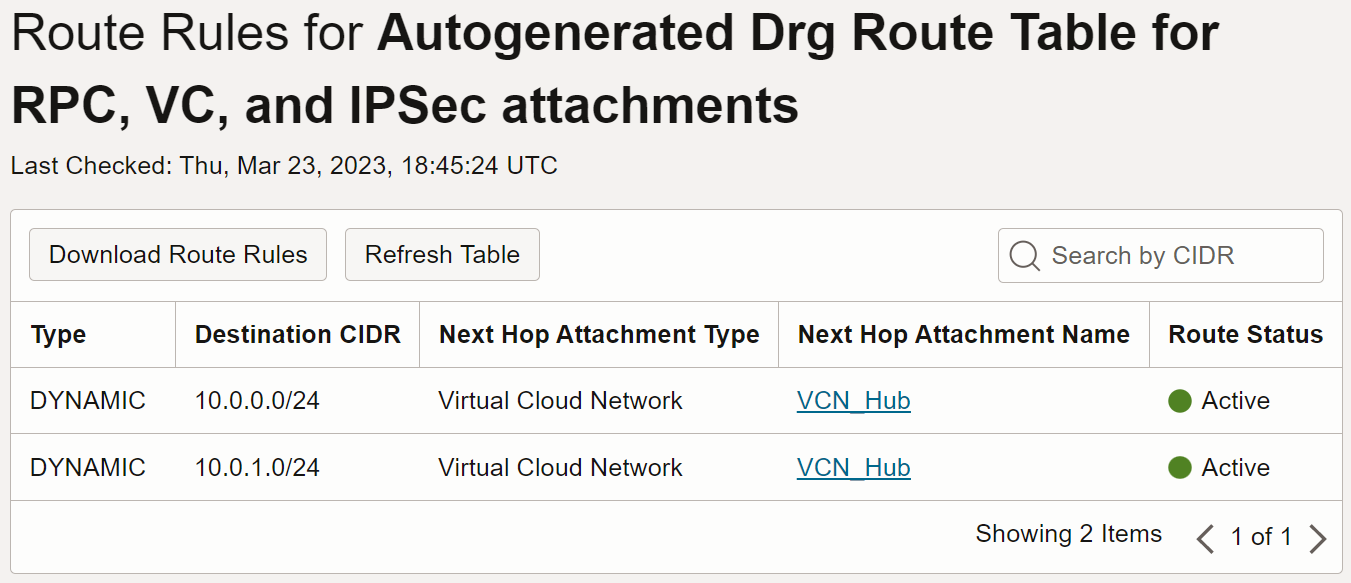
Image 3
The difference in that the Autogenerated DRG route Table for VCN attachments needs to have routes to VCNs, not for routing back to itself, but for routing to other VCNs that might also be attached to the same DRG, and they might need to route to each other. There can be up to 300 VCNs attached to one DRG!
When you configure an IPsec VPN connection from on-premises, or from another Cloud Service Provider, to OCI, for routing from the OCI side all you must do is configure the VCN to route to the DRG where both that VCN and the IPsec VPN connections are attached. See image 4.
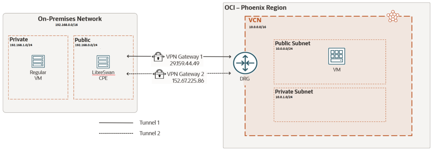
Image 4
If later the same VCN in OCI that is communicating to on-premises, also needs to communicate to a VCN that is in another OCI region, then an RPC is needed in the same DRG. Once the RPC is set, for communicating the VCN to the remote VCN, each VCN must add a route rule that targets their respective DRG. The overall setting will look like image 5.
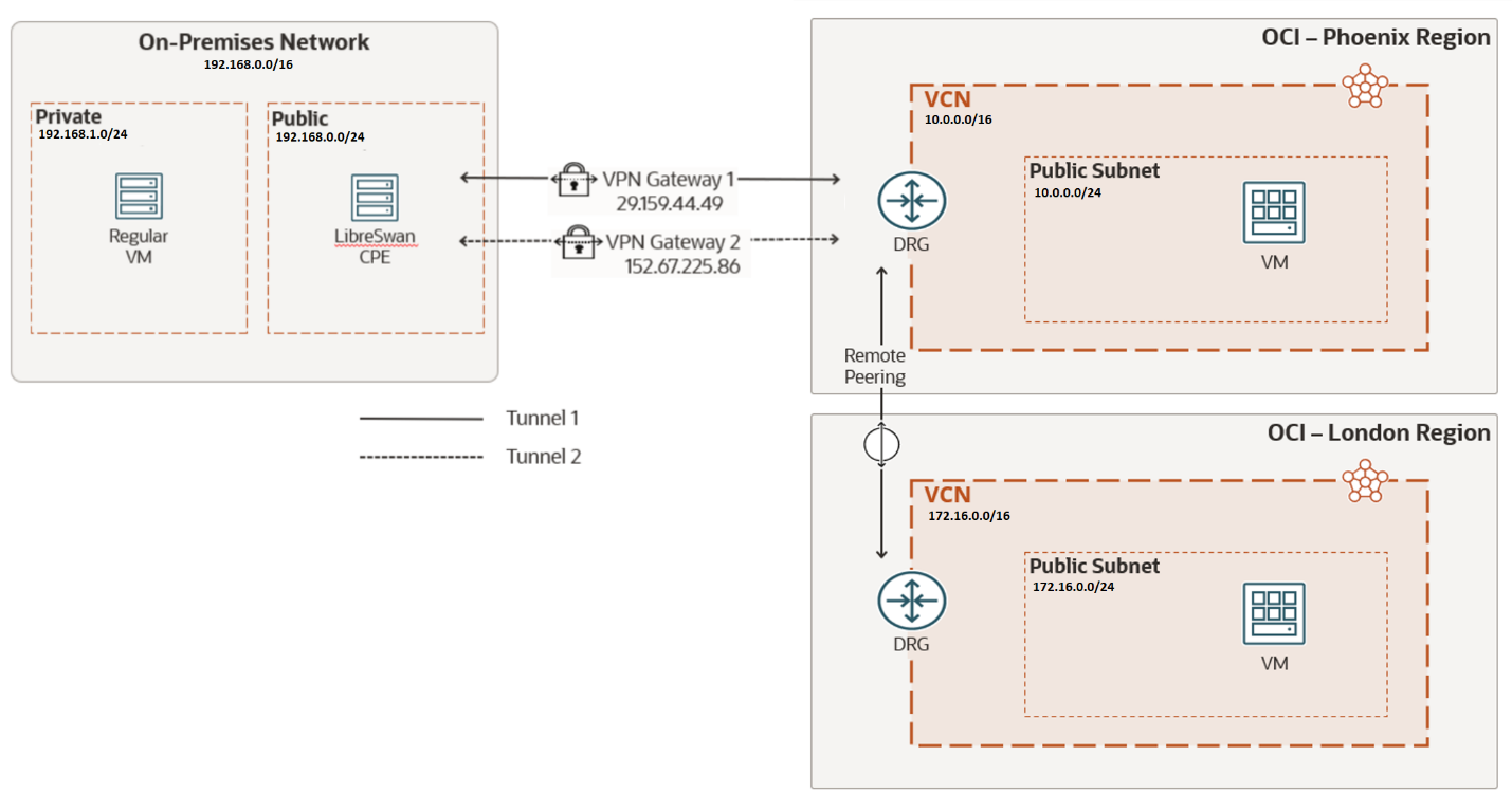
Image 5
This setting gives the impression that the DRG in the middle (Phoenix region) will automatically route traffic from on-premises to the remote region (London) just by adding the appropriate route rules to the route tables of both VCNs and the On-Premises LAN. This is transitive routing, and it is a feature of the DRG. But it is not automatic. You need to configure the route tables and route distributions of the DRG that will serve as a hub (DRG in the Phoenix region in image 5).
And the reason is quite simple, attaching resources to a DRG should not automatically add transitive routing as this might not be the intension for the attachments. If transitive routing, going from point A to point C via point B, is the goal; then it should be configured.
Summarizing what we have described above, in image 5, the VCN in Phoenix can communicate with the VCN in London via the Remote Peering Connection. At the same time the VCN in Phoenix can communicate with the On-Premises LAN via the Site-to-Site VPN connection. But the On-Premises LAN cannot communicate with the VCN in London via these two connections. Not yet.
Let’s configure transitive routing to make it happen.
The first thing that we will do is perform a deeper review of the Autogenerated route tables.
The Autogenerated Drg Route Table for RPC, VC, and IPSec attachments route table remains the same because it is the same route table for all three services, so adding the RPC didn’t change a thing in regards with route rules. Image 3 still represents it. This route table is associated with the Import Route Distribution: Autogenerated Import Route Distribution for VCN Routes where its match criteria is precisely Virtual Cloud Network. This means that any traffic coming from either the VPN or the RPC, it will only route to the VCN.
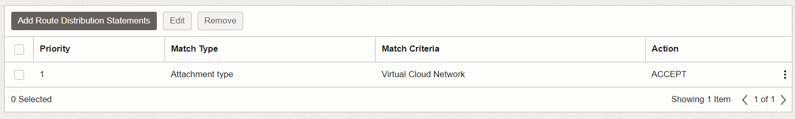
Image 6
On the other hand, the Autogenerated Drg Route Table for VCN attachments route table is associated with the Import Route Distribution: Autogenerated Import Route Distribution for ALL routes. This route distribution matches on all routes, without a match criteria.
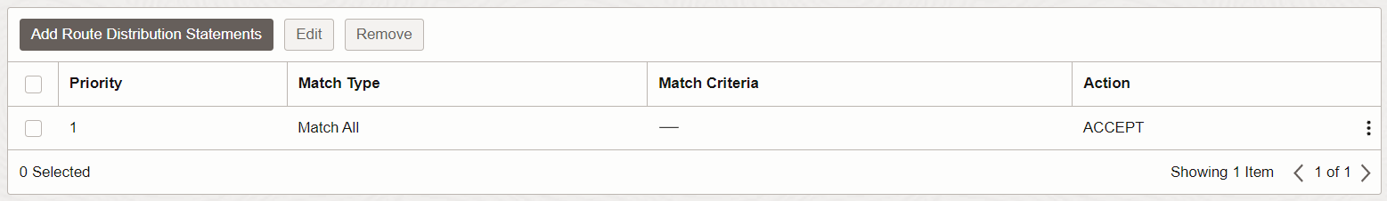
Image 7
This is the reason why the route table for the Autogenerated Drg Route Table for VCN attachments has routes to all attachments:
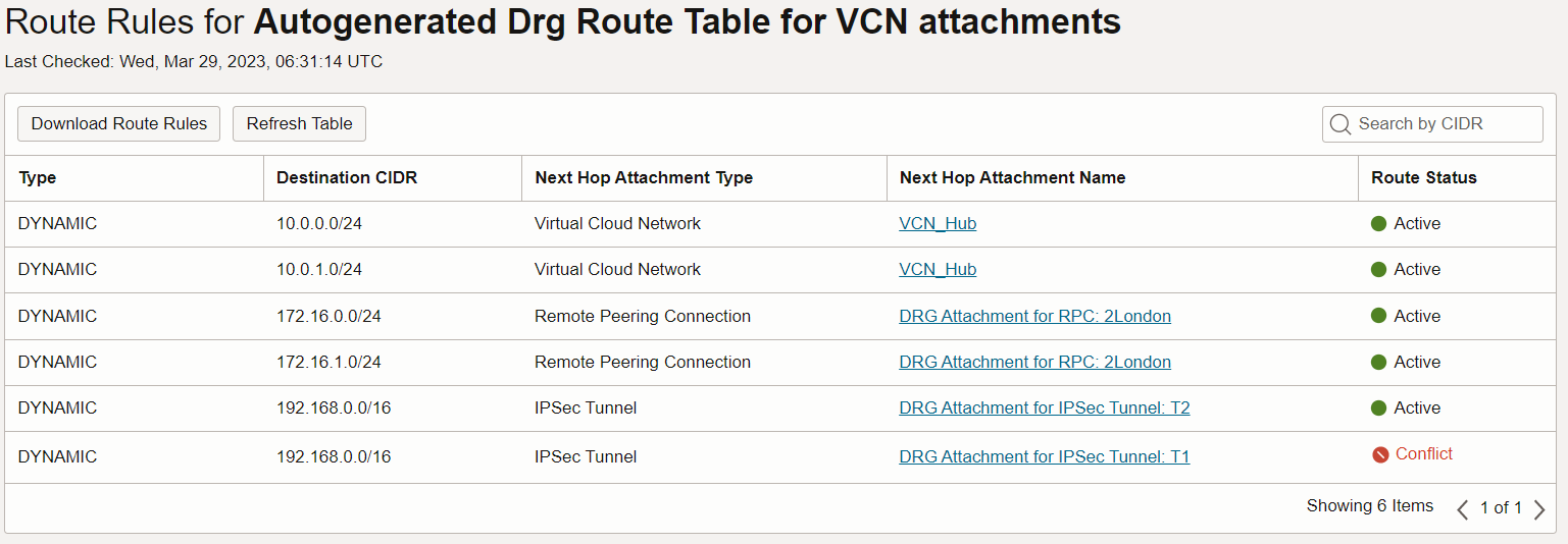
Image 8
This means that traffic coming from a VCN will route to any of these resources.
It is clear that traffic entering the DRG in Phoenix from the VPN will only route to the VCN in Phoenix. If we want to add a path that routes to the RPC we need to add a route distribution. And, allow me to be redundant:
It is clear that traffic entering the DRG in Phoenix from the RPC will only route to the VCN in Phoenix. If we want to add a path that routes to the VPN we need to add a route distribution.
CREATE THE VPN ROUTE DISTRIBUTION
- In the top right of the console header, make sure you are in the right region: US West (Phoenix).
- In the main menu, in Networking, click Dynamic Routing Gateway.
- Select your DRG.
- Under Resources click Import Route Distributions.
- Click Create Import Route Distribution.
- Name: RD-VPN
- Priority: 1
- Match Type: Attachment Type
- Attachment Type: IPSec Tunnel
- Click + Another Statement
- Priority: 2
- Match Type: Attachment Type
- Attachment Type: Virtual Cloud Network
- Click Create Import Route Distribution.
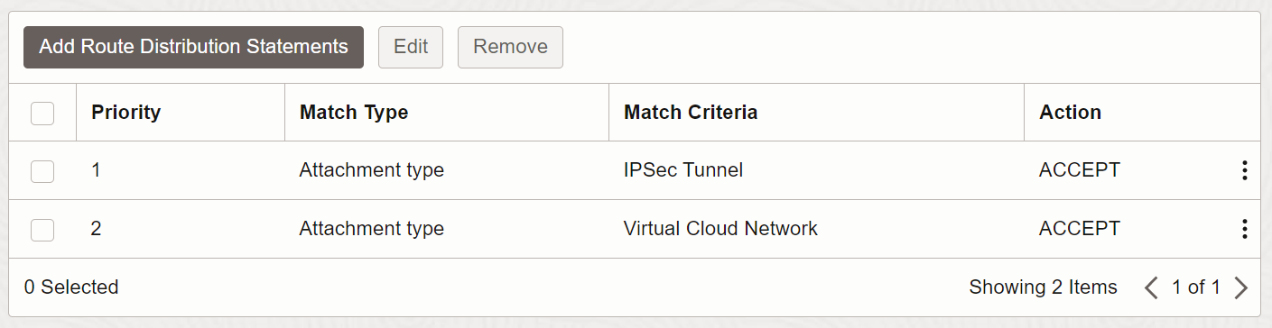
Image 9
Notice that the route distribution now routes to the IPSec Tunnel in addition to the VCN.
CREATE THE RPC ROUTE DISTRIBUTION
- Click Create Import Route Distribution again.
- Name: RD-RPC
- Priority: 1
- Match Type: Attachment Type
- Attachment Type: Remote Pearing Connection
- Click + Another Statement
- Priority: 2
- Match Type: Attachment Type
- Attachment Type: Virtual Cloud Network
- Click Create Import Route Distribution.
We also need to add route tables and associate them with a route distribution. Let’s create the route tables.
CREATE THE VPN ROUTE TABLE
- In the top right of the console header, make sure you are in the right region: US West (Phoenix).
- In the main menu, in Networking, click Dynamic Routing Gateway.
- Select your DRG.
- Under Resources click DRG Route Tables.
- Click Create DRG Route Table.
- Name: RT-VPN
- Click Show Advanced Options.
- Check the Enable Import Route Distribution checkbox. (Notice that here is where you can enable ECMP)
- In the Import Route Distribution field, select RD-RPC.
- Click Create DRG Route Table.
We just added a route table that when traffic enters the DRG from VPN. It will route traffic to the VCN and to the RPC.
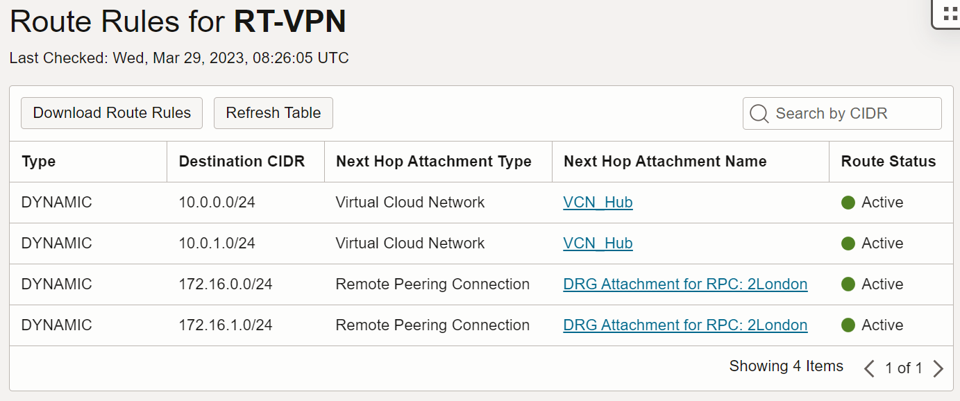
Image 10
CREATE THE RPC ROUTE TABLE
- Click Create DRG Route Table again.
- Name: RT-RPC
- Click Show Advanced Options.
- Check the Enable Import Route Distribution checkbox.
- In the Import Route Distribution field, select RD-VPN.
- Click Create DRG Route Table.
Now the VPN and RPC attachments need to be associated with the route tables that we just created. This is the final step for transitive routing
RPC ATTACHMENT ROUTE TABLE
- Under Resources click Remote Peering Connections Attachments.
- To the right of the RPC Attachment listed, right-click Actions Menu (three vertical dots).
- Select View Details.
- Click Edit.
- In the Choose a DRG Route Table drop-down list, select RT-RPC.
- Click Save Changes.
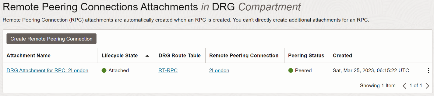
Image 11
VPN ATTACHMENTS ROUTE TABLE
- In the breadcrumbs area, click on your DRG
- Under Resources, click IPSec Tunnel Attachments.
- To the right of the first IPSec tunnel Attachment right-click the Actions Menu.
- Select View Details.
- Click Edit.
- In the Choose a DRG Route Table select RT-VPN.
- Click Save Changes.
- Repeat for the second IPSec tunnel Attachment.
CONCLUSION
Transitive Routing has been enabled! Now you can connect from the On-Premises LAN to the VCN in London via the DRG in Phoenix. Make sure that your respective VCNs have the appropriate Route Rules and Security List permissions.
Thanks to my colleagues Catalin Andrei and Eli Schilling for reviewing the draft of this post.