Introduction
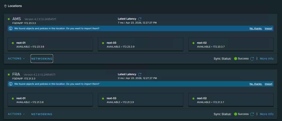
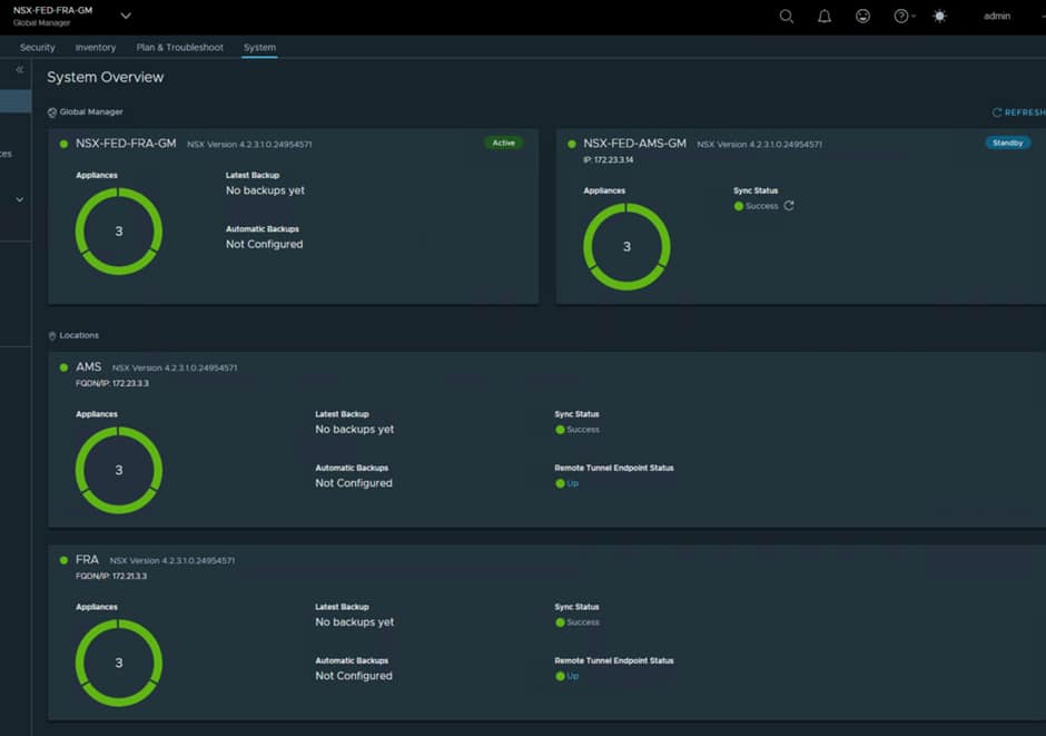
In Part 1 of this series, we deployed NSX Federation within Oracle Cloud VMware Solution (OCVS), introduced the Global Managers, registered our sites, and configured the foundational management components required for federation.
With the management plane now operational, we can begin to unlock the real value of NSX Federation: enabling workloads to communicate seamlessly across regions while maintaining centralized policy and operational consistency.
In this article, we will expand the architecture by deploying dedicated federation edge clusters, configuring federated Tier-0 and Tier-1 gateways, establishing cross-site connectivity, and enabling north-south routing for workloads running on stretched segments.
By the end of this guide, workloads deployed in either region on the same segment will be able to communicate with each other while also maintaining access to external networks and services.
Understanding the Federation Data Path
Before diving into the configuration, it is important to understand how traffic flows within a federated environment.
NSX Federation separates the management plane from the data plane. While the Global Manager provides centralized policy management and configuration, traffic forwarding continues to occur within the local NSX instances deployed at each site.
This architecture provides:
- Centralized networking and security policy management
- Consistent configuration across multiple sites
- Local traffic forwarding where appropriate.
- Regional resilience and failover capabilities
However, traffic forwarding behaviour depends on the networking constructs being used, particularly when stretched segments are involved.
Traffic Locality and Gateway Placement Considerations
One of the most important concepts to understand when designing a federated environment is how traffic is routed when using stretched segments.
Although NSX Federation provides a globally managed networking and security framework, stretched segments do not provide active-active gateway functionality. Instead, the segment gateway remains active within a single site, known as the active location.
As a result, workloads running in the non-active site must traverse the inter-site transport network using the Edge RTEPs to reach their default gateway before any routed traffic can be forwarded.
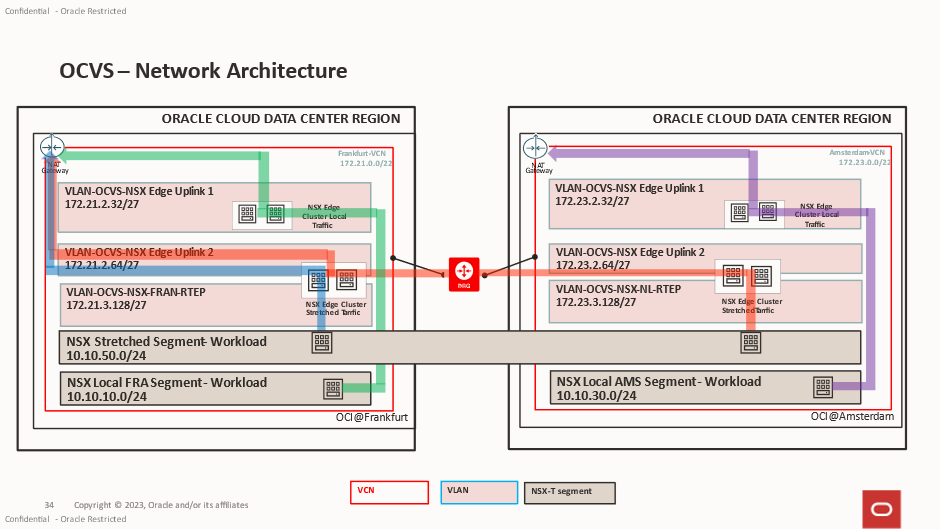
Consider the example below:
- A stretched segment exists between FRA and AMS.
- The segment gateway is active in FRA.
- A workload is running in AMS.
In this scenario, all routed traffic generated by the AMS workload must first traverse the inter-site transport network to FRA, where the gateway resides. Once routed, the traffic can then continue towards its destination.
The green line in the diagram below represents this traffic, it will be routed out via the T0 into the Edge Uplink 2 VLAN
The red line in the diagram below represents normal traffic flow between the 2 VMs in the same stretched segment.
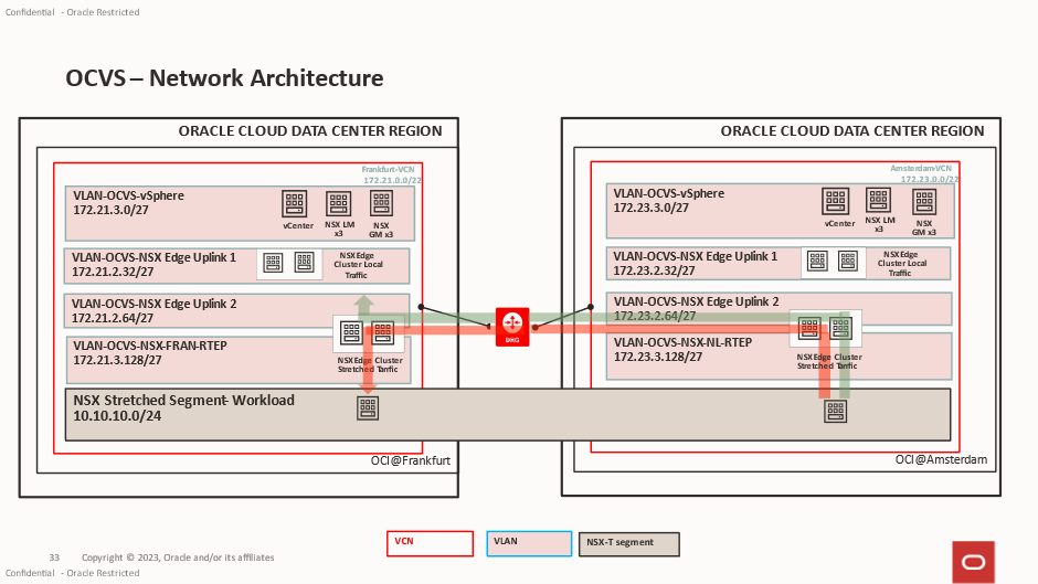
This behaviour is expected and forms part of the Federation design.
Understanding Traffic Tromboning
Because gateway ownership is maintained within a single site, traffic may not always take the shortest forwarding path.
For example:
- A workload resides in AMS.
- The stretched segment gateway is active in FRA.
- The workload attempts to access an internet resource.
- Traffic traverses from AMS to FRA.
- The packet is routed by the FRA gateway.
- Traffic exits via the FRA Tier-0 north-south connection.
This introduces what is commonly referred to as traffic tromboning, where traffic traverses the inter-site connection between the Edge clusters before being routed externally.
While this may not represent the most optimal forwarding path, it provides significant operational benefits:
- Consistent IP addressing across sites.
- Simplified workload mobility
- Reduced application reconfiguration during migrations
- Seamless disaster recovery workflows
Gateway Failover Behaviour
In the event of a site failure, gateway ownership can be transferred to the surviving location.
Once failover occurs:
- The surviving site becomes the active gateway location.
- Workloads continue operating using their existing IP addresses.
- North-south connectivity is restored through the surviving site’s Tier-0 gateway.
This capability is one of the key advantages of NSX Federation, allowing applications to maintain network consistency while supporting regional failover scenarios.
When designing federated architectures, it is important to balance the operational simplicity provided by stretched networking against the potential impact of traffic tromboning during normal day to day operations.
Deploying Additional Federation Edge Nodes
With the Federation control plane established, the next step is to deploy dedicated edge nodes to provide routing services for both inter-site communication and north-south traffic flows.
While Federation can leverage existing edge clusters, deploying dedicated federation edge nodes provides a cleaner separation of responsibilities and improves operational flexibility.
One thing that is easily missed is that in the NSX Limits it clearly states:
Logical Routing > Tier-0 Gateways per Edge Node = 1
Logical Routing > Tier-0 Logical Routers per Edge Node = 1
This can impact your decision on the number of Edge Nodes you would require for your deployment.
Benefits include:
- Dedicated capacity for federation services
- Improved scalability
- Simplified troubleshooting
- Better separation between local and federated routing functions
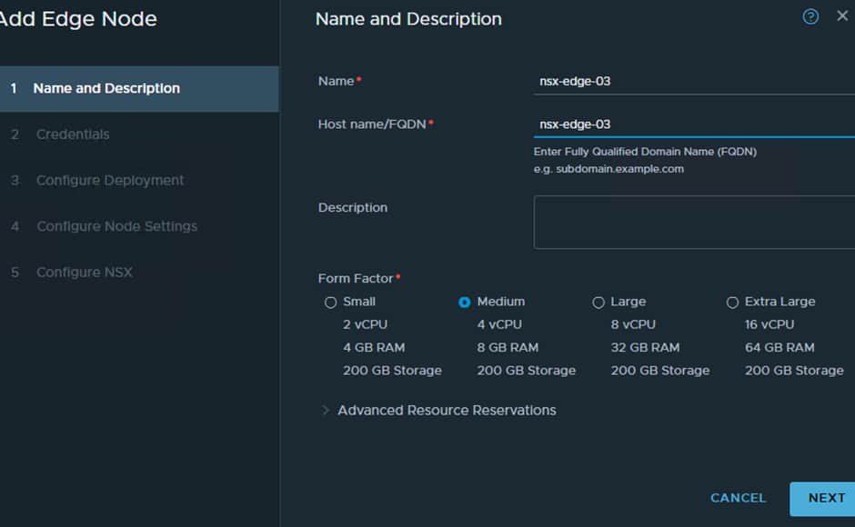
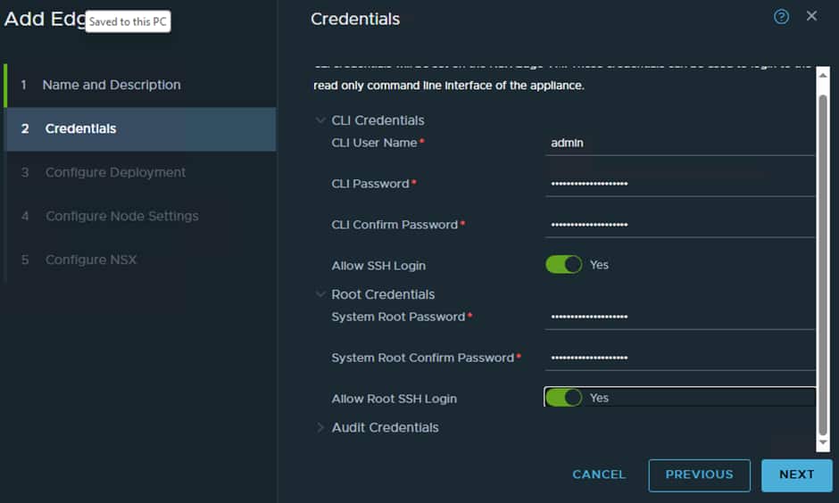
The deployment process follows the same approach as a standard NSX Edge deployment within OCVS.
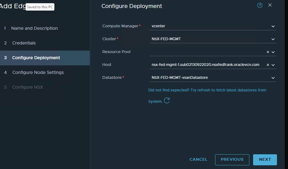
During deployment:
- Select the appropriate management network.
- Configure transport node profiles.
- Assign TEP addressing.
- Configure uplink interfaces for external connectivity.
Once deployed, verify:
- Edge nodes are healthy.
- TEP connectivity is operational.
- Transport node status is healthy.
- Federation services are realized successfully.
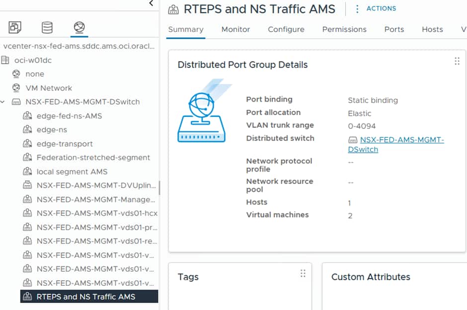
One of the first things we need to do is create a Trunk PG on the vCenter VDS, this will be used for the RTEPS and North South traffic.
Benefits include:
- Dedicated capacity for federation services
- Improved scalability
- Simplified troubleshooting
- Better separation between local and federated routing functions
The deployment process follows the same approach as a standard NSX Edge deployment within OCVS.
During deployment:
- Select the appropriate management network.
- Configure transport node profiles.
- Assign TEP addressing.
- Configure uplink interfaces for external connectivity.
Once deployed, verify:
- Edge nodes are healthy.
- TEP connectivity is operational.
- Transport node status is healthy.
- Federation services are realized successfully.
One of the first things we need to do is create a Trunk PG on the vCenter VDS, this will be used for the RTEPS and North South traffic.
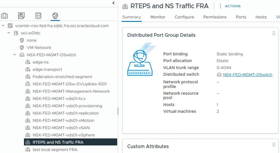
As you can see here it is set to trunk to allow (all) VLANs through. The Edge Nodes we deploy will patch into this and utilise VLAN tagging which is applied at the NSX Level. This needs to be mirrored at both sites.
Configuring RTEPs
Remote TEP (RTEP) interfaces are configured on each edge node within an edge cluster at a given site to enable stretched networking capabilities. These interfaces are only required when inter-site communication is needed. The RTEP must reside on a VLAN that is separate from the one used by standard edge TEP interfaces, and currently, each edge node supports only a single RTEP interface.
The traffic flow follows this path:
Host TEPs > Edge TEP > Edge RTEP > Remote Edge RTEP > Remote Host TEPs
After configuring RTEPs, every edge node in the cluster forms a full-mesh Geneve tunnel (used as an internal transport segment) with edge nodes in other sites. These tunnels carry heartbeat traffic to monitor the availability of remote edge nodes.
Earlier NSX-T versions used the hypervisor TEPs for cross site communication, hypervisor TEPs no longer create Geneve tunnels between sites for Layer 2 extension. Instead, all inter-site Layer 2 traffic is carried through tunnels established between RTEPs on the Edge Nodes. Each stretched Layer 2 segment is associated with an L2 forwarder component deployed on RTEP-enabled edge nodes. This L2 forwarder can operate in either Active/Standby or Active/Active mode, depending on the design. As a result, RTEP-enabled edge nodes handle inter-site traffic forwarding for the associated segments.
1. We need to create some IP Pools for the RTEPs.
At each Local Manager select IP Address Pools and create a pool for the RTEPs:
For Frankfurt we created:
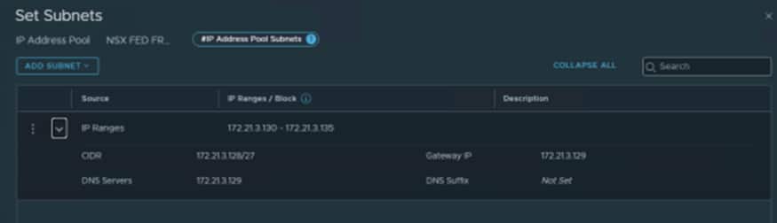
We used 172.21.3.130-172.21.3.135 as we know the VLAN we created earlier is 172.21.3.128/27.
The first IP is always the G/W so the first usable IP is .130
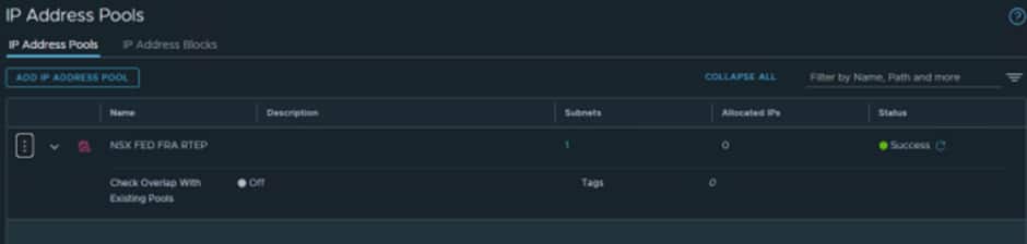
For Amsterdam we created:
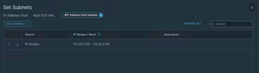
We used 172.23.3.130-172.23.3.135 as we know the VLAN we created earlier is 172.23.3.129/27.
The first IP is always the G/W so the first usable IP is .130
ℹ️ We created small pools for this test environment. If you know your production environment will need to scale, make sure to size the subnet on the underlying VLAN and IP Pools accordingly
Configuring New Edge Cluster
This process is very straightforward, and it will create two switches on the edge node, which will allow it to know how to route traffic. Each switch on the Edge Node uses its up VM uplink on the Edge Node.
- Uplink 1 is for the Management Network and is how the Edge Node communicates with NSX Manager
- Uplink 2 is used for Edge Transport traffic, between the local hosts/edge TEPs
- Uplink 3 is used for North South Traffic and for the RTEPs between sites.
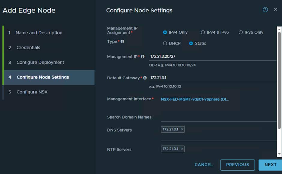
Here we need to give the vSphere Management network details, so we need to find a free IP to use. The vSphere Management network in the FRA SDDC is:

So, we know the G/W is the first IP which is 172.21.3.1 and DNS/NTP also uses the G/W IP.
Now we must create two switches on the Edge Node as follows:
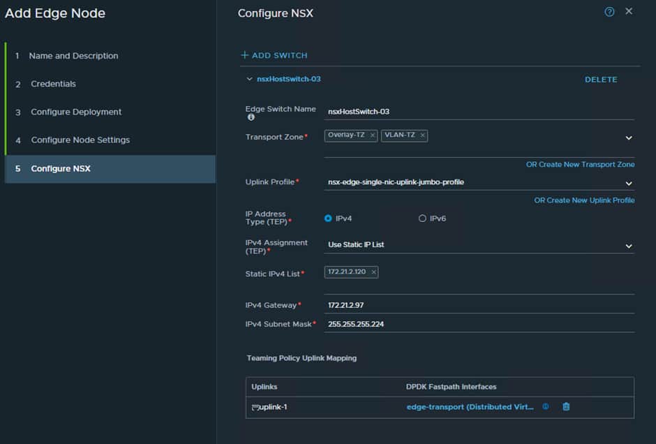
This will handle all local TEP traffic between the hosts and the edge nodes. So it requires an IP range from the EDGE VTEP VLAN:

We have used .120 for the interface and we know the first IP is the G/W which is .97.
Now we must configure a switch for the RTEP/ N/S traffic:
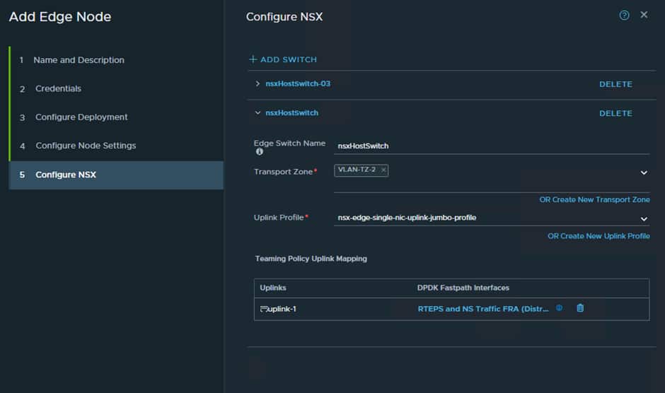
Now repeat this process again for the additional Edge Node and then do the same at the secondary site which in our case ins AMS.
The end result will look like this at both sites:
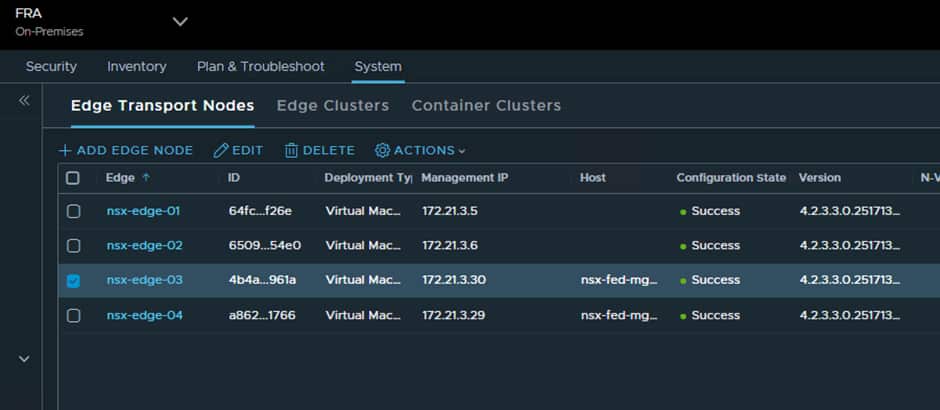
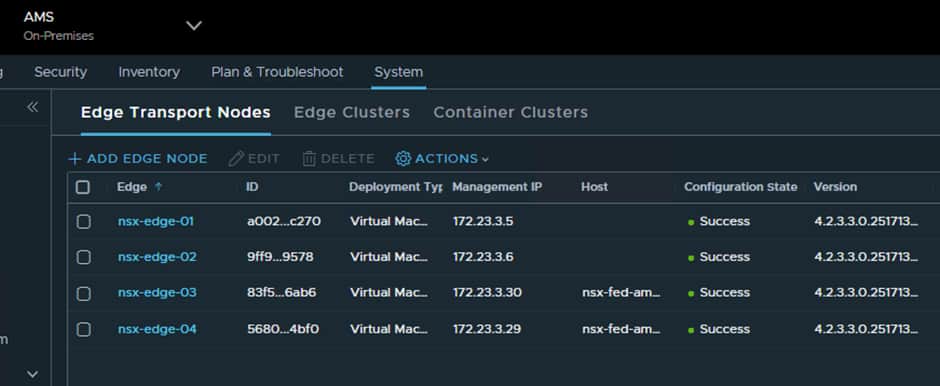
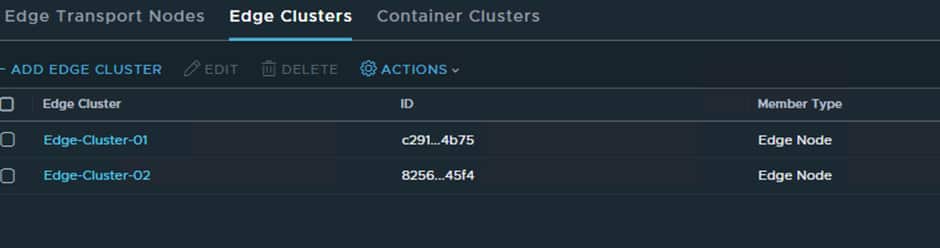
Now we just need to add the Edge Nodes to a new Edge Cluster:
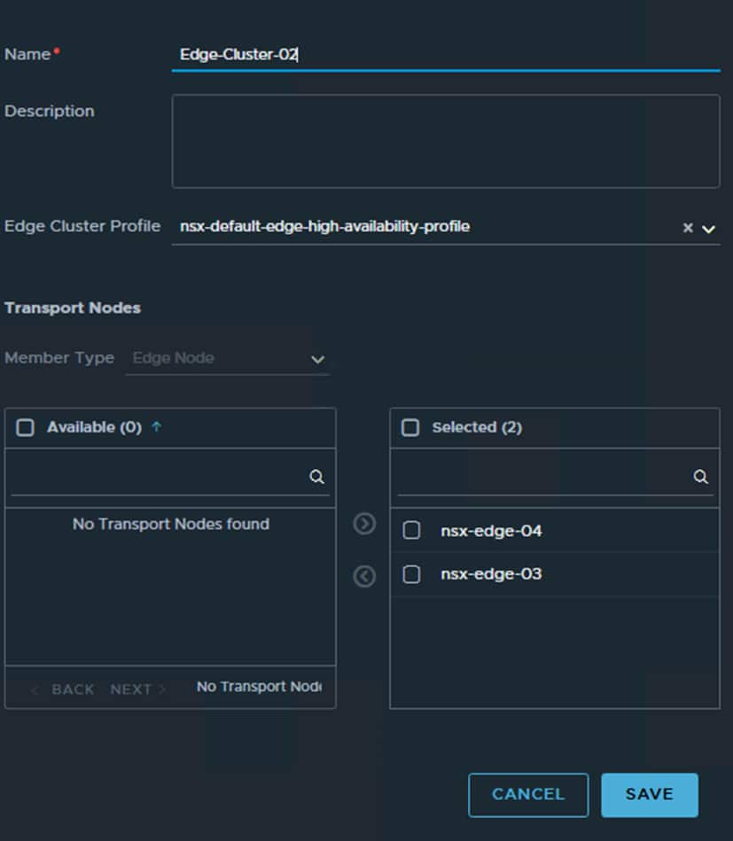
Once this has been done you will have 2 Edge Clusters at each site, one that handles local traffic only and the new Edge Cluster which will handle all cross-site traffic/segments.
Now that RTEP configuration and the Edge Nodes have been created, we can configure the cross-site networking:
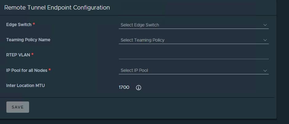
Now that has been done, we can configure the RTEPs from the Global Manager interface:
Select the Networking option from the interface:
You will then be taken to a wizard and input the required details:
- Edge Nodes
- Teaming Policy
- RTEP VLAN
- IP Pool
- MTU
Teaming Policy and MTU can be left at default.
Do this for both sites. Remember Edge-Cluster-01 remains unchanged we are adjusting Edge-Cluster-02.
When that has been completed you will notice a new system transport zone has been added to the edge nodes
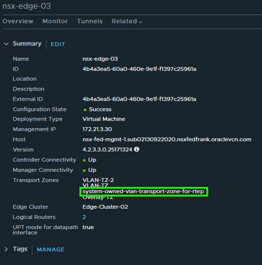
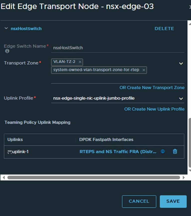
The new system RTEP transport Zone is attached to the Edge Node switch that handles RTEP and N/S traffic which is correct.
Now we need to set the Default Transport Zone at each local site:
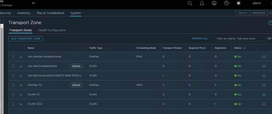
Ensure that Overlay-TZ is set to default, as that is what is configured for use with OCVS. You need to do this at both sites.
Once these are added in the Edges should be able to create a secure connection and start replicating traffic.
Creating T0/T1s
Creating Federated T0
The Federated Tier-0 Gateway provides the routing foundation for cross-site communication and north-south connectivity.
The Federated Tier-0 provides centralized configuration while allowing traffic forwarding to remain local to the active routing location.
Now that all the infrastructure has been creating, we are in a good spot to start creating our Logical Infrastructure.
The first thing we need to create a segment for each site in the Global Manager for use by the T0 Uplinks:
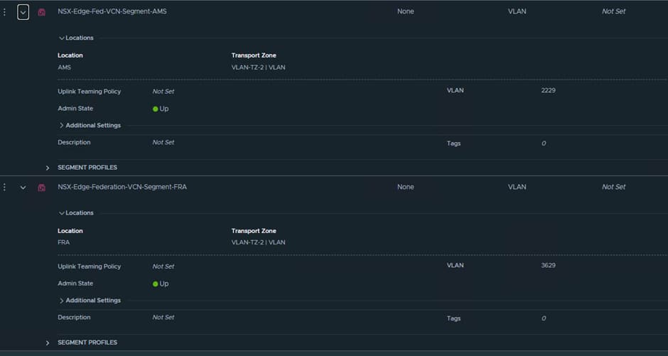

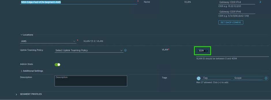

When creating these segments, it is key that you put in the correct VLAN ID, as NSX will tag the traffic for use by the VDS Trunk port we created earlier on.
The T0 Uplink interfaces will use IPs from this VLAN.
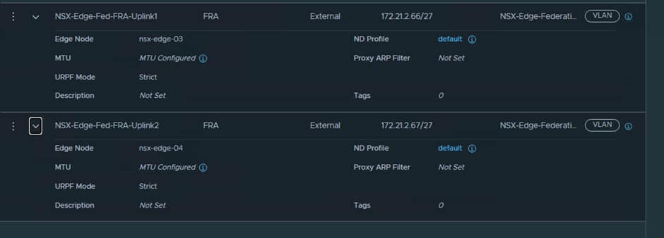
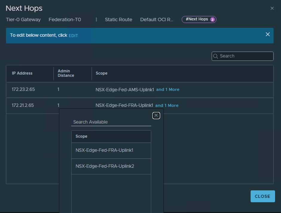
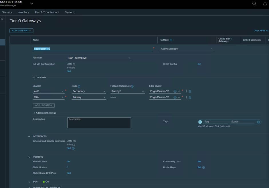
When creating the T0 you will have to define the Interfaces as shown below:
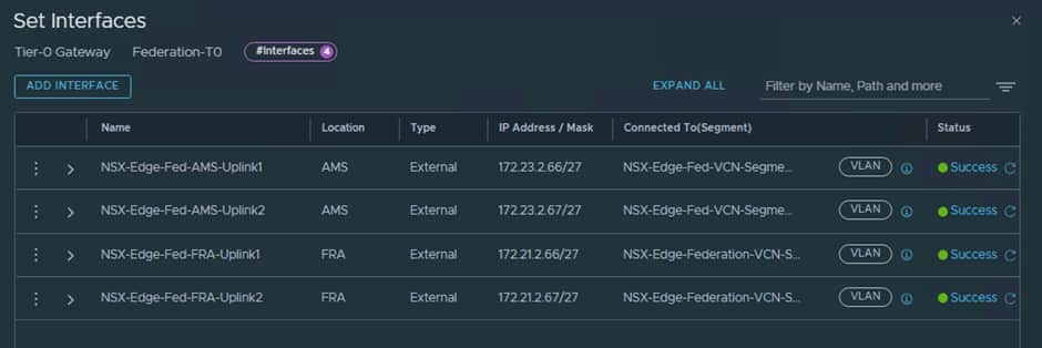
Uplink-1 will use nsx-edge-03 and Uplink 2 will use nsx-edge-04.
The IP addresses used are from a free range in the Uplink-2 VLAN, so in our case we are using .67 and .68
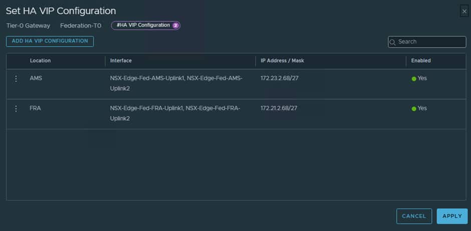
We now need to configure the HA VIP for the T0 and this will use .68


We now need to set up the static route to ensure all unknown traffic gets routed to the OCI “Uplink-2” VLAN’s gateway IP address.
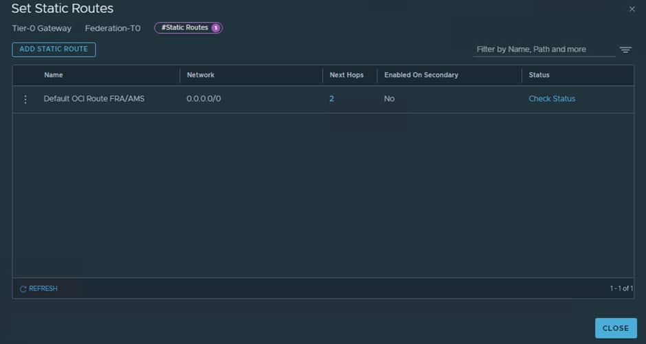


For both our OCI “Uplink-2” VLANs the gateway is the first IP which is .65
Next, we need to decide which location is going to be the Primary and which is Secondary for the T0, since AMS will be secondary in our deployment this can be configured at the T0 level.
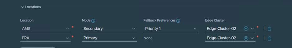
ℹ️ The Edge Nodes themselves are not active/standby, they are just nodes used to relay traffic, it is the T0/T1 that define the active/standby status.
The result should look something like this:
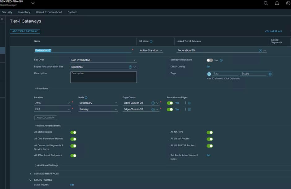
Creating T1
Tier-1 gateways provide segmentation and workload connectivity.
The Federated Tier-1 will serve as the routing boundary for stretched workload segments while inheriting centralized management through Federation.
Now create a T1 and link it to the T0, set it to use the same Edge-Cluster-02 and have FRA as Primary and AMS as Secondary.
Also ensure the correct Route Advertisements are configured some any segments you create on the T1 are advertised up to the attached T0.
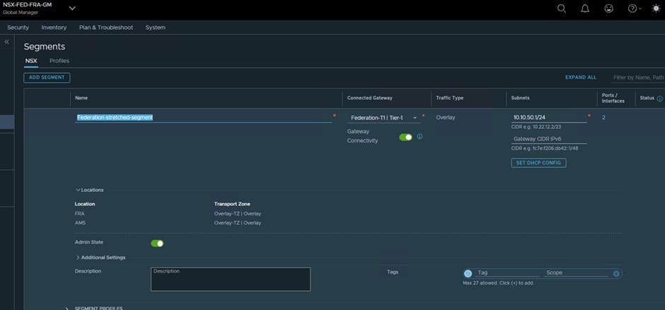
Creating Stretched Segments
With the routing infrastructure in place, we can create stretched segments that span both regions.
Stretched segments allow workloads to retain consistent IP addressing regardless of which site they are running within.
Benefits include:
- Simplified disaster recovery
- Reduced migration complexity
- Consistent addressing
- Improved workload mobility
Now it is time to create a Stretched Segment and for this I have used the 10.10.5.0/24 range.
Stretched segments must be created using the Global Manager.
We have 4 test VMs
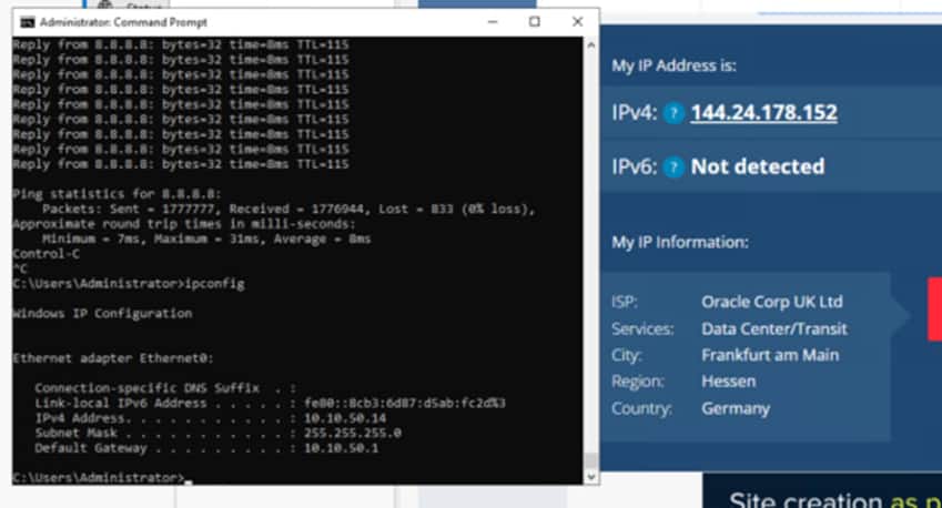
In the Stretched Segment we have 2 Windows VMs. The VM in FRA has an IP address of 10.10.50.12, the VM in AMS has an IP address of 10.10.50.14
In the FRA local segment, we have 1 VM with the IP address of 10.10.10.11
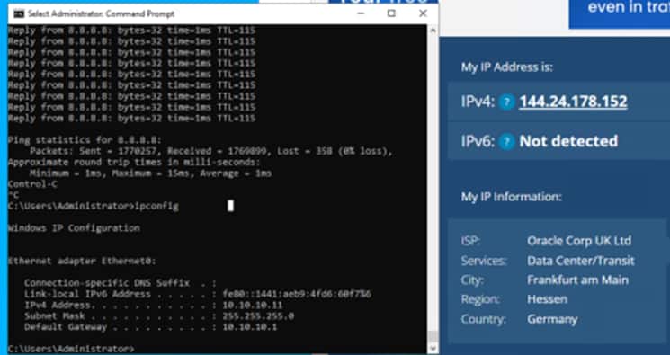
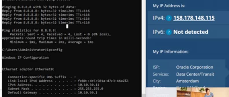
In the Ams local segment, with have 1 VM with an IP address of 10.10.30.11
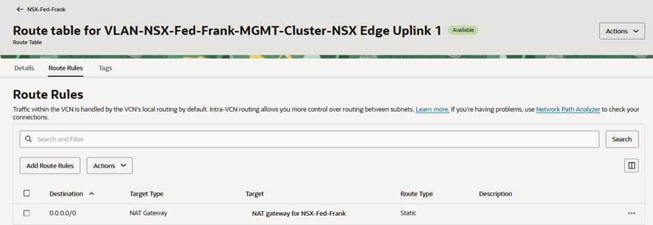
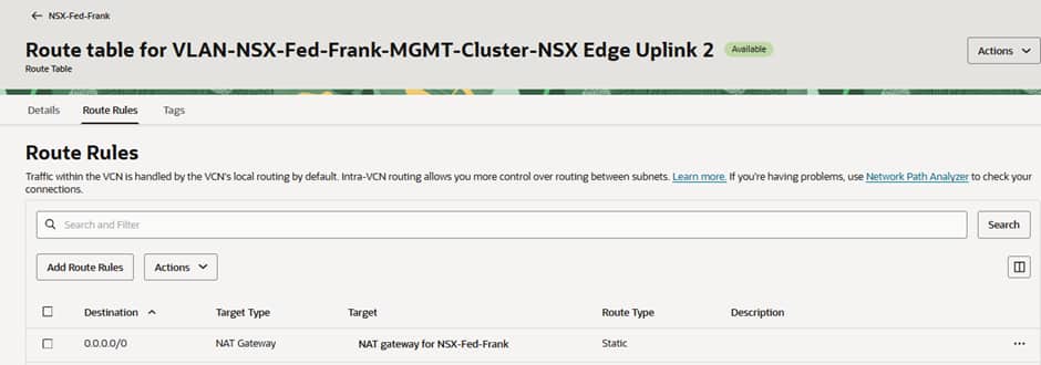
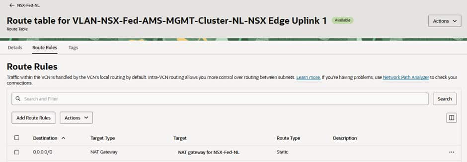
Traffic heading to the Internet from each VM is represented by a coloured line. In the VLAN route tables for Edge Uplink 1 and 2 at FRA and Edge Uplink 1 at AMS, we have pointed all traffic to go to the NAT G/W.
In the screenshots below you can see that the 0.0.0.0/0 routes for Uplink-1 (the “local” T0 gateway N/S connection) in each site and the same route for Uplink-2 (the federated “stretched” T0 gateway N/S connection) in the active (Frankfurt) site point to local OCI NAT Gateways in the respective sites’ VCNs.
In this screenshot we can see that our VM in the stretched segment in FRA is reaching the Internet through the OCI public IP of the NAT Gateway in FRA, and the latency is low.
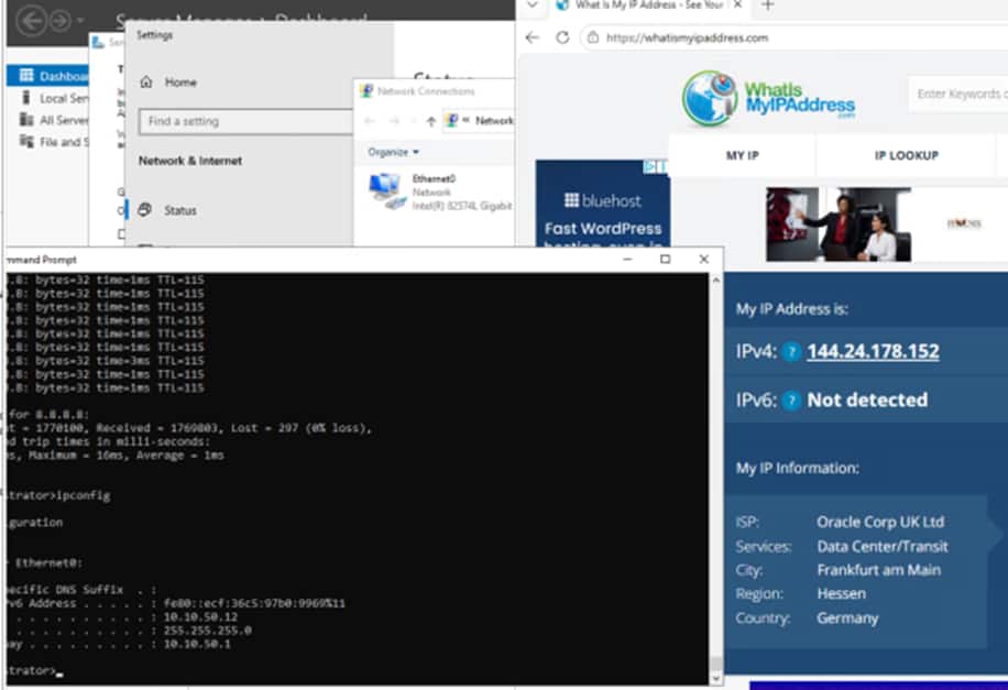
Whereas in the screenshot below we can see that our VM in the stretched segment in AMS is reaching the Internet through the SAME public IP in FRA, but the latency is higher, because its traffic is having to travel across regions via the RTEPs before breaking out to the Internet via the active T0 in Frankfurt.
For our VM in the local segment in FRA, we can see it resolves to the SAME public IP in FRA and the latency is low.
Unlike the VM in the stretched segment in AMS, our VM in the local segment in AMS reaches the Internet from a DIFFERENT public IP in AMS and the latency is low. This is expected as it is going to a local NAT G/W in the OCI datacentre in AMS.
Troubleshooting North-South Connectivity: “Dropped by NEIGH”
During the implementation of our lab environment, we encountered an issue where workloads on stretched segments could successfully communicate across sites but were unable to access external resources.
Initial testing showed that:
- Stretched segment connectivity was operational.
- Workloads could communicate between FRA and AMS.
- Federation services were healthy.
- Federated Tier-0 and Tier-1 gateways were successfully realized.
However, north-south traffic consistently failed.
To investigate further, we used NSX Traceflow to follow a packet generated from a workload on the stretched segment. The results showed the packet successfully traversing:
- The stretched segment.
- The Federated Tier-1 gateway.
- The inter-site transport network.
- The Federated Tier-0 gateway.
The packet was then dropped on the Edge uplink interface with the status:
Dropped by NEIGH
This message indicates that the Edge Node is unable to resolve the Layer 2 neighbour for the configured next hop. In practical terms, the Edge knows where the packet should be forwarded, but it cannot successfully perform ARP resolution for the upstream gateway.
When we logged into the Edge Node and had a look at the Uplink Interface we noticed:
  Interface     : 2e59b705-17cb-4ee9-a23e-74d4f520f3a4
    Ifuid         : 338
    Name          : NSX-Edge-Fed-FRA-Uplink1
    Fwd-mode      : IPV4_ONLY
    Internal name : uplink-338
    Mode          : lif
    Port-type     : uplink
    IP/Mask       : 172.21.2.68/27;172.21.2.66/27
    MAC           : 00:50:56:9a:c3:2e
    VLAN          : untagged
    Access-VLAN   : untagged
    LS port       : 1cd383b7-c24c-4438-8a94-c6c31dc3b8c4
    Urpf-mode     : STRICT_MODE
    DAD-mode      : LOOSE
VLAN : untagged
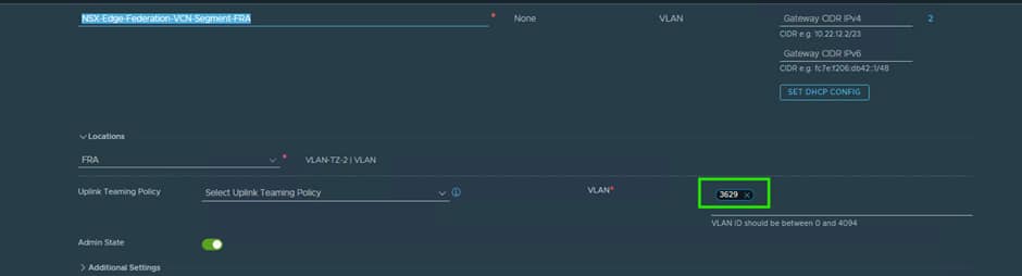
After validating the routing configuration, uplink IP addressing, and gateway settings, we discovered that the VLAN ID had not been configured correctly on the NSX uplink segment.
Because the Edge uplink segment was connected to a trunk port group on the vSphere Distributed Switch, NSX was responsible for applying the VLAN tag before traffic left the Edge Node. Without the correct VLAN assignment, packets reached the uplink interface but could not communicate with the upstream gateway, resulting in failed neighbour resolution.
The issue was resolved by assigning the correct VLAN ID to the uplink segment used by the Federated Tier-0 gateway.
Once this was done when we logged into the Edge Node and had a look at the Uplink Interface we noticed:
Interface     : 2e59b705-17cb-4ee9-a23e-74d4f520f3a4
    Ifuid         : 338
    Name          : NSX-Edge-Fed-FRA-Uplink1
    Fwd-mode      : IPV4_ONLY
    Internal name : uplink-338
    Mode          : lif
    Port-type     : uplink
    IP/Mask       : 172.21.2.68/27;172.21.2.66/27
    MAC           : 00:50:56:9a:c3:2e
    VLAN          : 3629
    Access-VLAN   : untagged
    LS port       : 1cd383b7-c24c-4438-8a94-c6c31dc3b8c4
    Urpf-mode     : STRICT_MODE
    DAD-mode      : LOOSE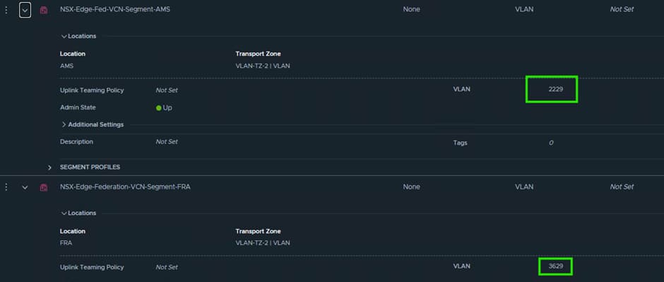
With the VLAN tagging now corrected:
- ARP resolution completed successfully.
- The upstream gateway became reachable.
- North-south routing was restored.
- Internet connectivity was established from both local and stretched workloads.
This serves as a useful reminder that when deploying federated Edge clusters in OCVS, uplink VLAN configuration is just as important as the logical routing configuration itself. A single VLAN mismatch can result in otherwise healthy Federation services appearing operational while all north-south traffic silently fails.
When troubleshooting similar issues, NSX Traceflow should be one of the first tools used, as it quickly identifies the exact point within the forwarding path where traffic is being dropped.
Acknowledgments
Co-Author:

Steve Dockar
Global Lead OCVS Solutions Architect
VMware by Broadcom
Contributors:
Ryan Veino – Master Principal Cloud Specialist OCVS
Alex Rodriguez – OCVS SRE