Part 1 – Deploying and configuring the initial components
Introduction
As organizations move toward multi-region and hybrid cloud architectures, maintaining consistent networking and security policies across locations becomes increasingly complex. This is where VMware NSX Federation becomes a powerful solution.
NSX Federation allows customers to centrally manage networking and security policies across multiple NSX deployments (sites) using the Global Managers, while enforcement happens locally on Local Managers.
The main benefits of NSX Federation are:
- Centralised policy control
- Consistent security posture across sites
- Simplified disaster recovery and mobility
Within Oracle Cloud VMware Solution (OCVS), NSX Federation is especially valuable because it enables you to extend your software-defined network across multiple SDDCs or regions while still maintaining operational control from a single pane of glass for your overlay networks within NSX.
Why NSX Federation in OCVS?
OCVS (with VCF BYOL licensing) provides the full VMware SDDC stack running natively on Oracle Cloud infrastructure. When combined with NSX Federation, you enable:
- Multi-region application deployment
- Disaster recovery with consistent networking
- Centralised security policy enforcement
- Workload mobility across SDDCs
Instead of configuring each NSX environment independently, Federation ensures that networking constructs (Tier-0, Tier-1, segments, firewall rules) can be defined once and applied globally.
So you can use Region specific VLANs for direct access into native OCI services and use NSX Overlay segments for all your VMware workloads, giving you the flexibility to run things as required by your business.
Core Components of NSX Federation
Global Manager (GM) – This just like the local manager is deployed as 3 VMs at each site. One site is Primary, and the other(s) are standby. It is the control plane for Federation. The customer must deploy these from the ova after SDDC deployment.
Defines global objects like:
• Tier-0 / Tier-1 gateways
• Segment
• Security policies
Local Manager (LM) – 3 Local Managers are deployed as part of the standard SDDC deployment.
Responsible for:
• Realizing configurations pushed from the Global Manager
• Managing local enforcement and state
NSX Federation Requirements
Key things to consider:
- To support NSX Federation, your environment must meet various requirements, including round-trip time, software versions, and ports.
- There must be a maximum round-trip time of 500 ms between the following nodes:
- Active Global Manager and standby Global Manager.
- Global Manager and Local Manager.
- Local Manager and remote Local Manager if you have cross-location security configuration only and VMware NSX® Edge Nodes RTEP and remote Edge Nodes RTEP if you have cross-network configurations.
- The Global Manager and Local Manager appliances must all have NSX 3.1.0 or later installed. All appliances in an NSX Federation environment must have the same version installed.
- The required ports must be open to allow communication between the Global Manager and Local Manager. See VMware Ports and Protocols at https://ports.broadcom.com/home/NSX.
- There must be connectivity without NAT between the following nodes:
- Global Manager and Local Manager.
- Local Manager and remote Local Manager.
- Edge node RTEP and remote Edge node RTEP.
Deploying the SDDCs
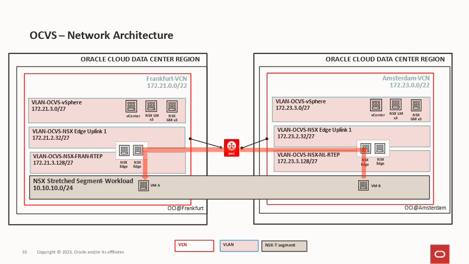
This is the end state we are aiming for:
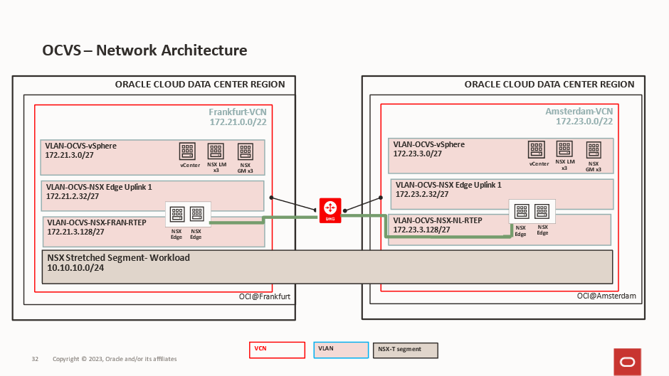
In our deployment, we are deploying 2 identical SDDCs, one if Frankfurt and one in Amsterdam.
The Frankfurt VCN is using 172.21.0.0/22.

The Frankfurt SDDC is using 172.21.2.0/23.
The Amsterdam VCN is using 172.23.0.0/22.

The Amsterdam SDDC is using 172.23.0.0/23.
After the SDDCs have been created, we need to create one additional VLAN at each site, and this is for the Edge RTEPs. This is what will allow the edge nodes to communicate with each other and send traffic between sites.
Frankfurt will use 172.21.3.128/27 VLAN 1407

Amsterdam will use 172.23.3.128/27 VLAN 3909

Each VLAN has its own route table and Network Security Group and both VCNs are attached to a local DRG and the DRGs are peered for cross regional routing.
If we investigate the route table and the Network Security Groups for these 2 VLANs we will see:
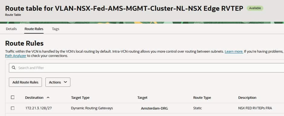
Frankfurt has a route to the DRG for the Amsterdam RTEP CIDR:
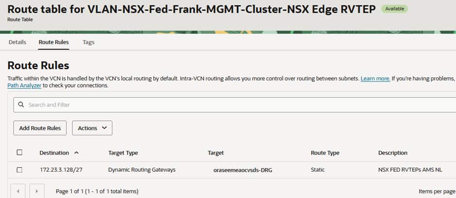
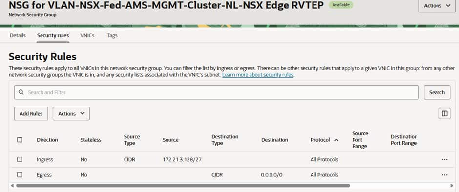
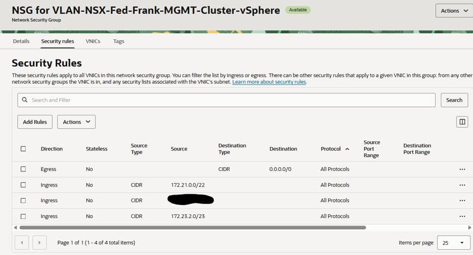
The Network Security Group (NSG) has 2 rules, one allowing traffic to ingress from the Amsterdam’s RTEPs and another allowing all egress.
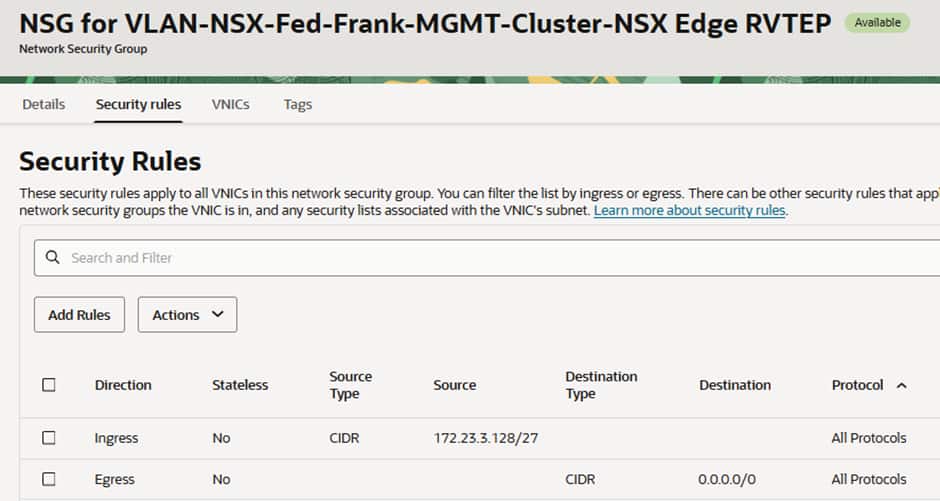
Amsterdam has a route to the DRG for the Frankfurt CIDR:
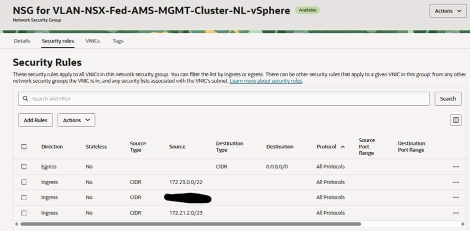
The Network Security Group (NSG) has 2 rules, one allowing traffic to ingress from the Amsterdam’s RTEPs and another allowing all egress.
Depending on your security policy and requirements you could make these tighter but for our testing purposes these are acceptable, you can consult https://ports.broadcom.com/home/NSX for further information.
Deploying The NSX Global Managers
3 Global Managers need to be deployed in each SDDC, alongside the already deploys 3 Local Managers created as part of the SDDC deployment.
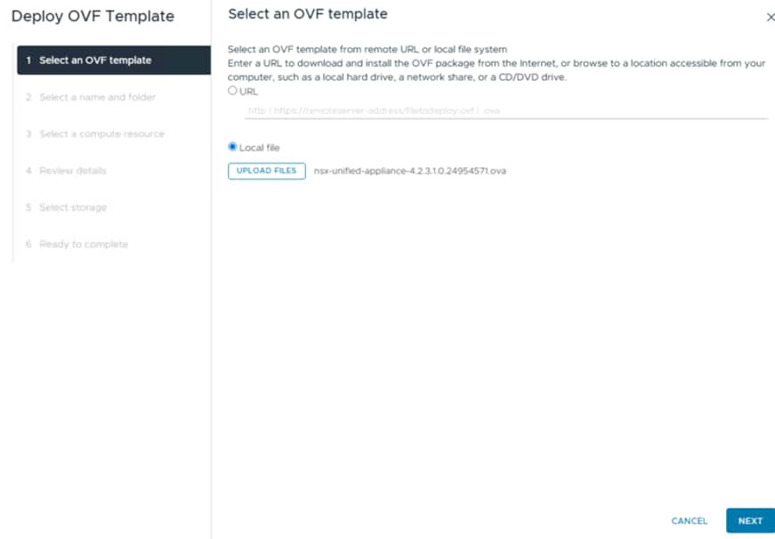
The first Global manager is deployed via OVA in the vCenter:
Select the required size for your manager:
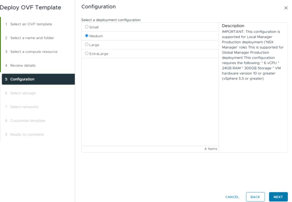
The network we will be deploying into is the vSphere network:
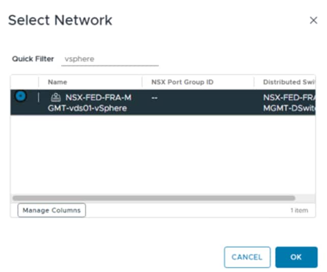
The reason for this is that all the VMware Management components for the SDDC are deployed into this network by default, so this will make communication easy between the Local Managers, Global Managers and the vCenter/ESXi hosts.
The key thing to select is the Global Manager option:
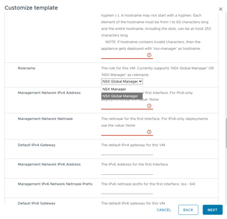
This ensures you deploy the Global Manager from the OVA and not another Local Manager.
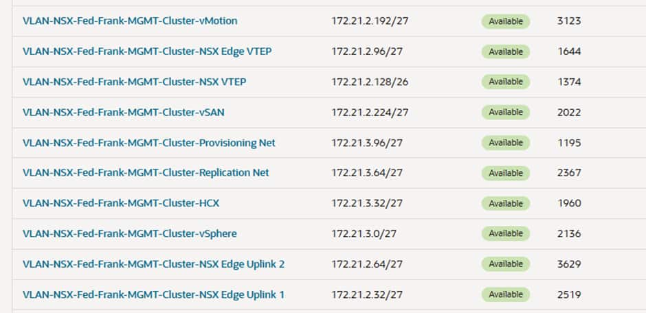
Remember that with OCVS VLANs, the first usable IP is always the Gateway, and this IP is also used for DNS and NTP. So the vSphere VLAN in Frankfurt is 172.21.3.0/27 and 172.21.3.1 is the G/W. Everything is statically assigned, there is no DHCP so you will have to find unused IPs to use.
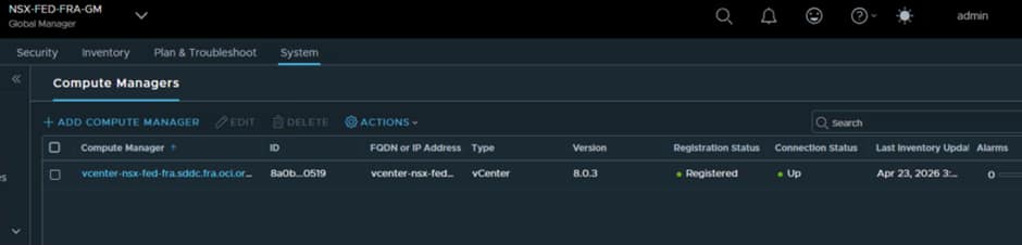
Once that has been deployed and powered on, login to the Global Manager using the username admin and the password you have provided during deployment.
Add the vCenter as a Compute Manager into the Global Manager:
Now we can deploy the remaining 2 Global Managers from the Global manager Interface using the Add NSX Appliance option:
You will then need to configure the VIP, as this is what will be referenced for everything.
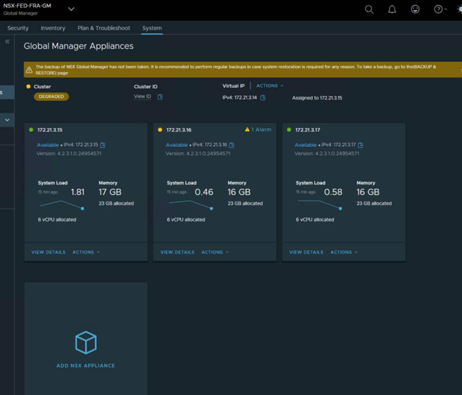
For Frankfurt we have configured the following:
- Nsx-fra-gm vip 172.21.3.14
- Nsx-fra-gm1 172.21.3.15
- Nsx-fra-gm2 172.21.3.16
- Nsx-fra-gm3 172.21.3.17
Now follow the exact same process at the other site.
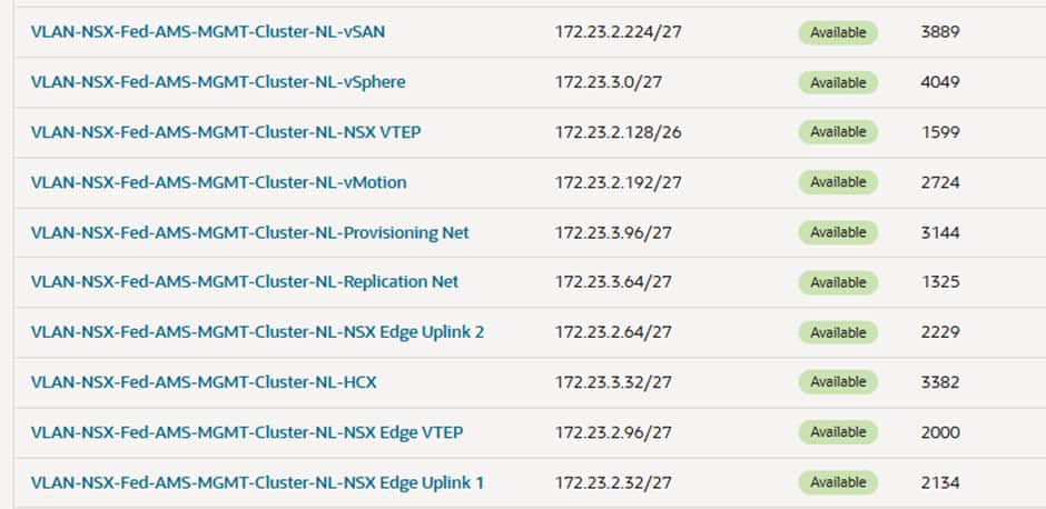
We have configured the following in Amsterdam.
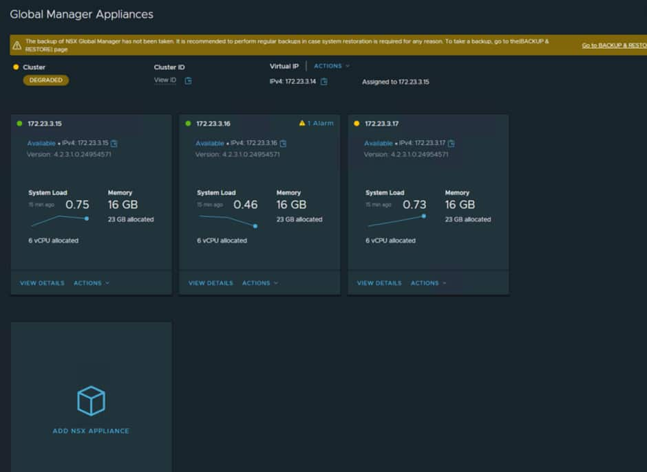
NSX Global Manager Installed @Amsterdam
- Nsx-fed-ams-gm vip 172.23.3.14
- Nsx-fed-ams-gm1 172.23.3.15
- Nsx-fed-ams-gm2 172.23.3.16
- Nsx-fed-ams-gm3 172.23.3.17
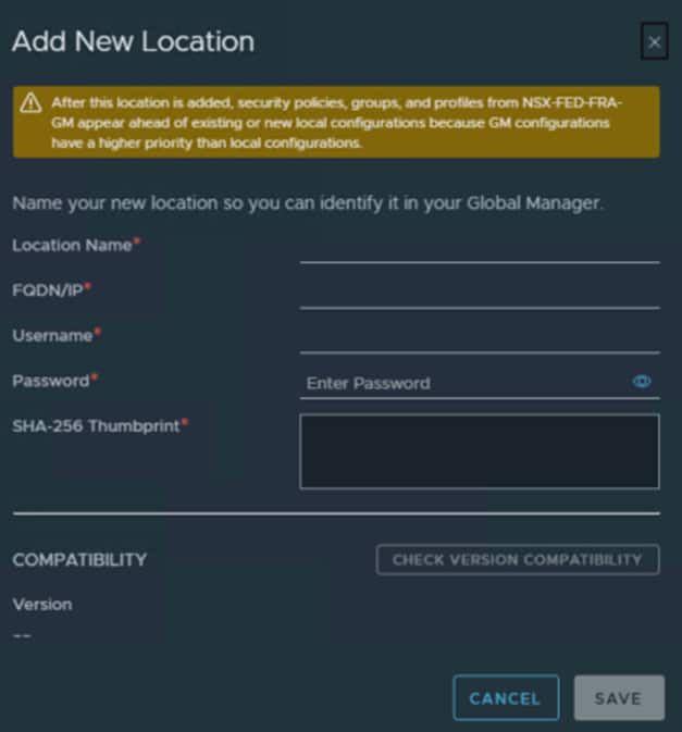
In our deployment Frankfurt will be the primary site so we need to add the Amsterdam Global Manager as a standby. You do this from the interface in Frankfurt and you must use the VIP for the remote site Global manager.
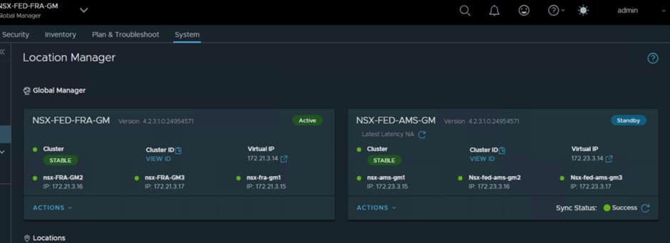
Once this has been completed, a sync operation will happen and you may see a few odd error messages while the sync happens, but these should clear after a few minutes.
If you are unable to do this part and receive errors, it is most likely down to the routing and NSG rules in the vSphere VLAN at both sites. The route tables need to be able to route traffic to the DRGs and the NSGs need to be able to allow the correct traffic through.
In the Frankfurt vSphere VLAN we have:
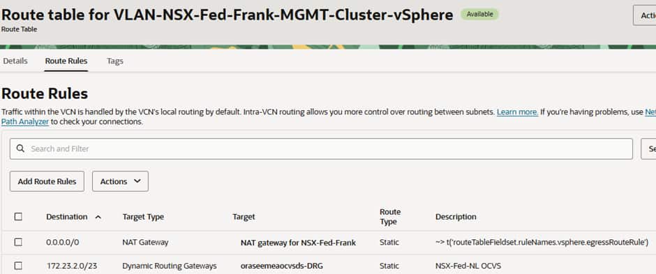
All traffic for the Amsterdam OCVS environment going to the local Distributed Routing Gateway (DRG).
The NSG is configured to allow all traffic from both deployments to have access and all egress to flow.
In the Amsterdam vSphere VLAN we have:
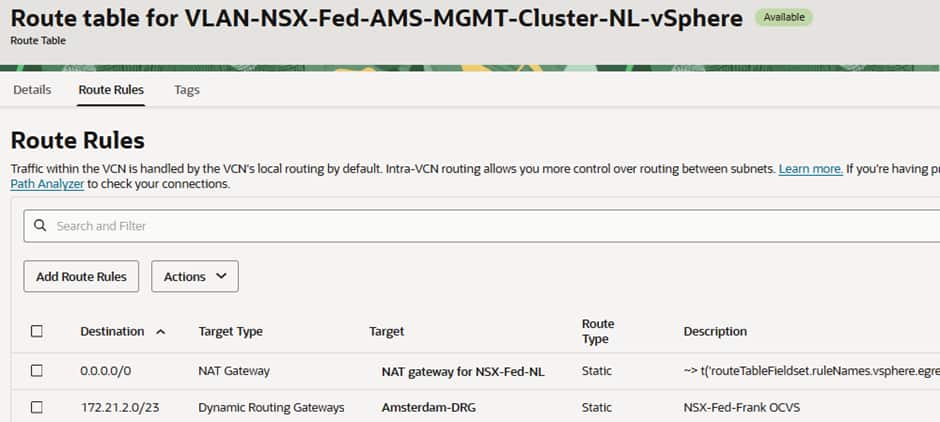
All traffic for the Frankfurt OCVS environment going to the local DRG.
The NSG is configured to allow all traffic from both deployments to have access and all egress to flow.
Adding in the Local Managers from both sites
From the Active Global Manager (in our case Frankfurt) we can add in the Local managers for both sites:

You must use the VIP for the NSX Local Manager Cluster
You can add both sets of Local Managers via the Primary Global Manager and once that has been done you should see:
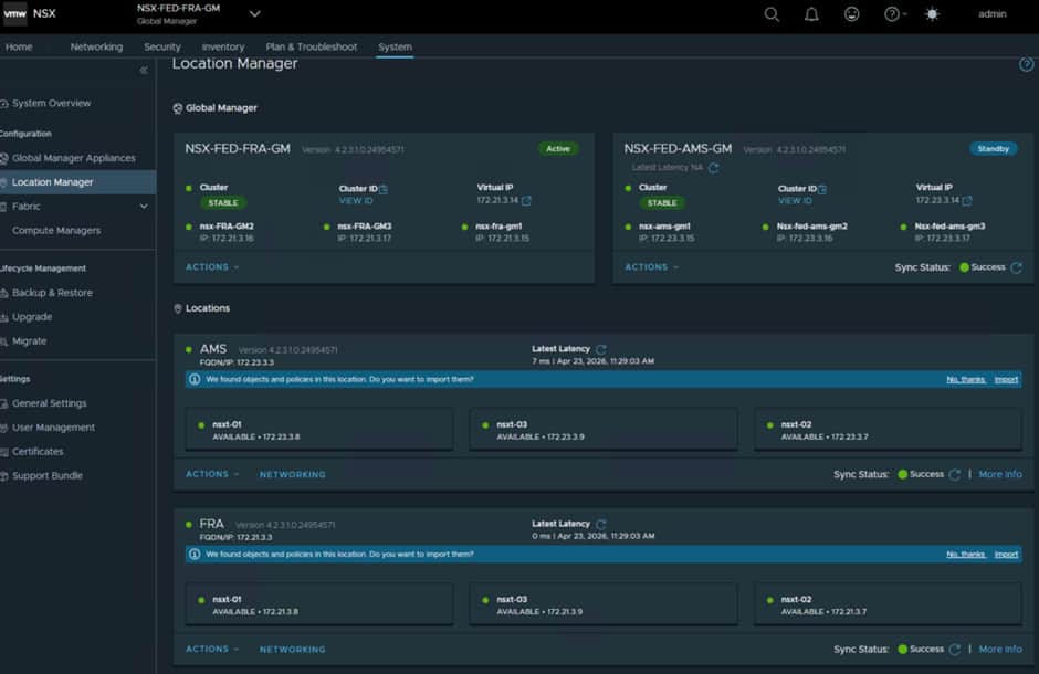
As with the Global Managers, a sync happens, and this can take a few minutes to complete and until then you may see some odd errors which is normal and expected.
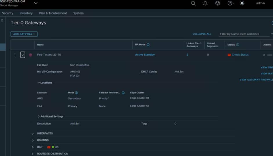
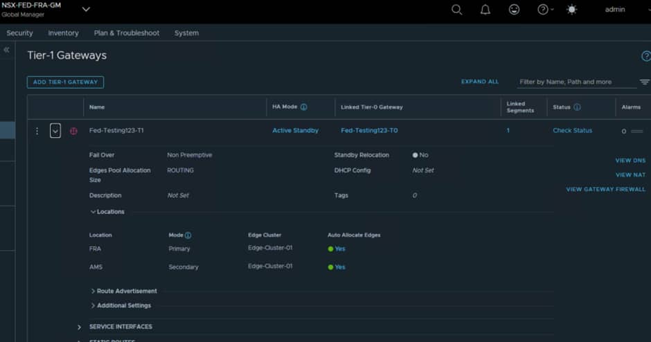
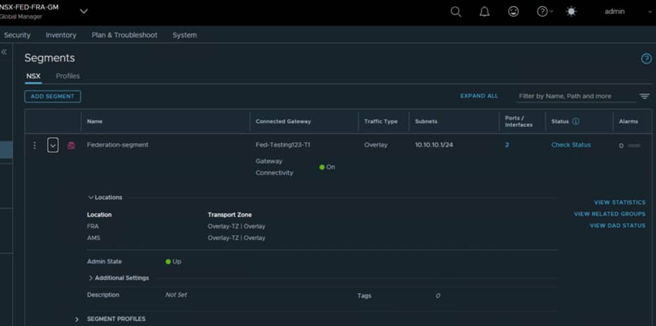
In the next blog post we will discuss deploying additional Edge Nodes and configuring the RTEPs for Federation and we will configure stretched T0/T1 and segments, examples of which are shown below:
VM Traffic Flows
Cross Site VM communication
We will discuss this in more detail in the next parts of this series, but for VMs that need to communicate across sites, within the same segment, the traffic will need to traverse the edge nodes, as the edge nodes are the only way the sites are connected together at the networking level.
There is a latency impact from that, so this could impact your decision as to where to place workloads.
Acknowledgments
Contributors: Steve Dockar (Broadcom) and Adeel Amin