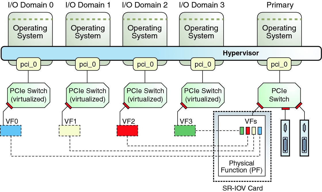
SR-IOV – Single Root IO Virtualization, is a PCI Express standard developed and published by the PCI-SIG. The idea here is that each PCIe card capable of SR-IOV, also called a “physical function”, can create multiple virtual copies or “virtual functions” of itself and present these to the PCIe bus. There, they appear very similar to the original, physical card and can be assigned to a guest domain very similar to a whole slot in case of DirectIO. The domain then has direct hardware access to this virtual adapter. Support for SR-IOV was first introduced to LDoms in version 2.2, quite a while ago. Since SR-IOV very much depends on the capabilities of the PCIe adapters, support for various communication protocols was added one by one, as the adapters started to support this. Today, LDoms support SR-IOV for Ethernet, Infiniband and FibreChannel. Creating, assigning or de-assigning virtual functions (with the exception of Infiniband) is dynamic since LDoms version 3.1 which means you can do all of this without rebooting the domains affected.
All of this is well documented, not only in the LDoms Admin Guide, but also in various blog entries, most of them by Raghuram Kothakota, one of the chief developers for this feature. However, I do want to give a short example on how this is configured, pointing to a few things to note as we go along.
Just like with DirectIO, the first thing you want to do is an inventory of what SR-IOV capable hardware you have in your system:
We’ve discussed this example earlier, this time let’s concentrate on the four last lines. Those are physical functions (PF) of two network devices (/SYS/MB/NET0 and NET2). Since there are two PFs for each device, we know that each device actually has two ports. (These are the four internal ports of a T4-2 system.) To dynamically create a virtual function of one of these ports, we first have to turn on IO Virtualization on the corresponding PCI bus. Unfortunately, this is not (yet) a dynamic operation, so we have to reboot the domain owning that bus once. But only once. So let’s do that now:root@sun:~# ldm ls-io NAME TYPE BUS DOMAIN STATUS ---- ---- --- ------ ------ pci_0 BUS pci_0 primary pci_1 BUS pci_1 primary niu_0 NIU niu_0 primary niu_1 NIU niu_1 primary /SYS/MB/PCIE0 PCIE pci_0 primary EMP /SYS/MB/PCIE2 PCIE pci_0 primary OCC /SYS/MB/PCIE4 PCIE pci_0 primary OCC /SYS/MB/PCIE6 PCIE pci_0 primary EMP /SYS/MB/PCIE8 PCIE pci_0 primary EMP /SYS/MB/SASHBA PCIE pci_0 primary OCC /SYS/MB/NET0 PCIE pci_0 primary OCC /SYS/MB/PCIE1 PCIE pci_1 primary EMP /SYS/MB/PCIE3 PCIE pci_1 primary EMP /SYS/MB/PCIE5 PCIE pci_1 primary OCC /SYS/MB/PCIE7 PCIE pci_1 primary EMP /SYS/MB/PCIE9 PCIE pci_1 primary EMP /SYS/MB/NET2 PCIE pci_1 primary OCC /SYS/MB/NET0/IOVNET.PF0 PF pci_0 primary /SYS/MB/NET0/IOVNET.PF1 PF pci_0 primary /SYS/MB/NET2/IOVNET.PF0 PF pci_1 primary /SYS/MB/NET2/IOVNET.PF1 PF pci_1 primary
root@sun:~# ldm start-reconf primary
Initiating a delayed reconfiguration operation on the primary domain.
All configuration changes for other domains are disabled until the primary
domain reboots, at which time the new configuration for the primary domain
will also take effect.
root@sun:~# ldm set-io iov=on pci_1
------------------------------------------------------------------------------
Notice: The primary domain is in the process of a delayed reconfiguration.
Any changes made to the primary domain will only take effect after it reboots.
------------------------------------------------------------------------------
root@sun:~# reboot
Once the system comes back up, we can check that everything went well:
root@sun:~# ldm ls-io
NAME                                      TYPE   BUS      DOMAIN   STATUS
----                                      ----   ---      ------   ------
pci_0                                     BUS    pci_0    primary
pci_1                                     BUS    pci_1    primary  IOV
[...]
/SYS/MB/NET2/IOVNET.PF1                   PF     pci_1    primary
As you can see, pci_1 now shows “IOV” in the Status column. We can use the “-d” option to ldm ls-io to learn a bit more about the capabilities of the PF we intend to use:
root@sun:~# ldm ls-io -d /SYS/MB/NET2/IOVNET.PF1
Device-specific Parameters
--------------------------
max-config-vfs
    Flags = PR
    Default = 7
    Descr = Max number of configurable VFs
max-vf-mtu
    Flags = VR
    Default = 9216
    Descr = Max MTU supported for a VF
max-vlans
    Flags = VR
    Default = 32
    Descr = Max number of VLAN filters supported
pvid-exclusive
    Flags = VR
    Default = 1
    Descr = Exclusive configuration of pvid required
unicast-slots
    Flags = PV
    Default = 0 Min = 0 Max = 32
    Descr = Number of unicast mac-address slots
All of these capabilities depend on the type of adapter and the driver that supports it. In this example case, we can see that we can create up to 7 VFs, the VFs support a maximum MTU of 9216 bytes and have hardware support for 32 VLANs and 32 MAC addresses. Other adapters are likely to give you different values here.
Now we can create a virtual function (VF) and assign it to a guest domain. We have to do this with a currently unused port – creating VFs doesn’t work while there’s traffic on the device.
root@sun:~# ldm create-vf /SYS/MB/NET2/IOVNET.PF1
Created new vf: /SYS/MB/NET2/IOVNET.PF1.VF0
root@sun:~# ldm add-io /SYS/MB/NET2/IOVNET.PF1.VF0 mars
root@sun:~# ldm ls-io /SYS/MB/NET2/IOVNET.PF1
NAME                                      TYPE   BUS      DOMAIN   STATUS
----                                      ----   ---      ------   ------
/SYS/MB/NET2/IOVNET.PF1                   PF     pci_1    primary
/SYS/MB/NET2/IOVNET.PF1.VF0               VF     pci_1    mars
The first command here tells the hypervisor, or actually, the NIC located at /SYS/MB/NET2/IOVNET.PF1, to create one virtual function. The command returns and reports the name of that virtual function. There is a different variant of this command to create multiple VFs in one go. The second command then assigns this newly create VF to a domain called “mars”. This is an online operation – mars is already up and running Solaris at this point. Finally, the third command just shows us that everything went well and mars now owns the VF.
Used with the “-l” option, the ldm command tells us some details about the device structure of the PF and VF:
root@sun:~# ldm ls-io -l /SYS/MB/NET2/IOVNET.PF1
NAME                                      TYPE   BUS      DOMAIN   STATUS
----                                      ----   ---      ------   ------
/SYS/MB/NET2/IOVNET.PF1                   PF     pci_1    primary
[pci@500/pci@1/pci@0/pci@5/network@0,1]
    maxvfs = 7
/SYS/MB/NET2/IOVNET.PF1.VF0               VF     pci_1    mars
[pci@500/pci@1/pci@0/pci@5/network@0,81]
    Class properties [NETWORK]
        mac-addr = 00:14:4f:f8:07:ad
        mtu = 1500
Of course, we also want to check if and how this shows up in mars:
root@mars:~# dladm show-phys
LINK              MEDIA                STATE      SPEED  DUPLEX    DEVICE
net0              Ethernet             up         0      unknown   vnet0
net1              Ethernet             unknown    0      unknown   igbvf0
root@mars:~# grep network /etc/path_to_inst
"/virtual-devices@100/channel-devices@200/network@0" 0 "vnet"
"/pci@500/pci@1/pci@0/pci@5/network@0,81" 0 "igbvf"
As you can see, mars now has two network interfaces. One, net0, is a more conventional, virtual network interface. The other, net1, uses the VF driver for the underlying physical device, in our case igb. Checking in /etc/path_to_inst (or, if you prefer, in /devices), we can now find an entry for this network interface that shows us the PCIe infrastructure now plumbed into mars to support this NIC. Of course, it’s the same device path as in the root domain (sun).
So far, we’ve seen how to create a VF in the root domain, how to assign this to a guest and how it shows up there. I’ve used Ethernet for this example, as it’s readily available in all systems. As I mentioned earlier, LDoms also support Infiniband and FibreChannel with SR-IOV, so you could also add a FC HBA’s VF to a guest domain. Note that this doesn’t work with just any HBA. The HBA itself has to support this functionality. There is a list of supported cards maintained in MOS.
There are a few more things to note with SR-IOV. First, there’s the VFs identity. You might not have noticed it, but the VF created in the example above has it’s own identity – it’s own MAC address. While this seems natural in the case of Ethernet, it is actually something that you should be aware of with FC and IB as well. FC VFs use WWNs and NPIV to identify themselves in the attached fabric. This means the fabric has to be NPIV capable and the guest domain using the VF can not layer further software NPIV-HBAs on top. Likewise, IB VFs use HCAGUIDs to identify themselves. While you can choose Ethernet MAC-addresses and FC WWNs if you prefer, IB VFs choose their HCAGUIDs automatically. If you intend to run Solaris zones within a guest domain that uses a SR-IOV VF for Ethernet, remember to assign this VF additional MAC-addresses to be used by the anet devices of these zones.
Finally I want to point out once more that while SR-IOV devices can be moved in and out of domains dynamically, and can be added from two different root domains to the same guest, they still depend on their respective root domains. This is very similar to the restriction with DirectIO. So if the root domain owning the PF reboots (for whatever reason), it will reset the PF which will also reset all VFs and have unpredictable results in the guests using them. Keep this in mind when deciding whether or not to use SR-IOV. If you do, consider to configure explicit domain dependencies reflecting these physical dependencies. You can find details about this in the Admin Guide. Development in this area is continuing, so you may expect to see enhancements in this space in upcoming versions.
Since it is possible to work with multiple root domains and have each of those root domains create VFs of some of their devices, it is important to avoid cyclic dependencies between these root domains. This is explicitly prevented by the ldm command, which does not allow a VF from one root domain to be assigned to another root domain.
We have now seen multiple ways of providing IO resources to logical domains: Virtual network and disk, PCIe root complexes, PCIe slots and finally SR-IOV. Each of them have their own pros and cons and you will need to weigh them carefully to find the correct solution for a given task. I will dedicate one of the next chapters of this series to a discussion of IO best practices and recommendations. For now, here are some links for further reading about SR-IOV:
- Raghuram’s Blog entries about SR-IOV
- Initial announcement for LDoms version 2.2
- Solaris11 VNICs on SR-IOV Virtual Functions
- OVM Server for SPARC 3.1 introduces Dynamic SR-IOV feature
- Direct I/O and SR-IOV features are now extended to Non-Primary root domains
- Announcement of Fibre Channel SR-IOV
- Live migration of a Guest with an SR-IOV VF using dynamic SR-IOV feature
- SR-IOV in the Admin Guide
- Youtube video by Intel about Ethernet SR-IOV
This is nice to get a basic understanding of SR-IOV, although it is very x86 oriented and many details don’t apply to SPARC.