What are PCI Express AER errors about?
When an error happens, we panic. Or grow concerned, at least. Even more so if we see an error message that is hard to understand. Unfortunately, PCI Express error reports belong to this category. The logs are detailed and technical, and without a specification in hand, we can’t easily tell how serious they are. It’s difficult to say if “Correctable Errors” should worry us or not.
To understand the meaning of these messages, we have to learn the basics of the PCI Express architecture and analyze how the devices in this protocol communicate with one another. With that, we are well equipped to explore different types of errors and learn about the Advanced Error Reporting (AER) feature, and observe how it is used to communicate issues with the PCI Express interface. After such an introduction, we will take a look at how the Linux kernel supports AER and how we can interact with it.
A Quick PCI Express Primer
PCI Express (PCIe) is a high performance, general purpose I/O bus that interconnects a wide range of peripheral devices, such as graphic cards, disk drives and network cards. It is also a protocol that describes the way devices communicate using serial point-to-point connections. Such a connection is a building block of the PCI Express infrastructure, and it is called a Link. Depending on the context, it can refer to the physical link between the two components, or a logical path used to transfer data. The physical Links consist of Lanes, pairs of two-way Transmit-Receive signals. There can be more than one pair in a Link. This is what x1, x2, or x16 refers to; it’s the number of pairs of signals within a Link. This defines the “width” of the connection. Multiple devices can be connected together using a switch, which receives and forwards data to other PCI Express components. Links in the switch are internal and have no physical manifestation.
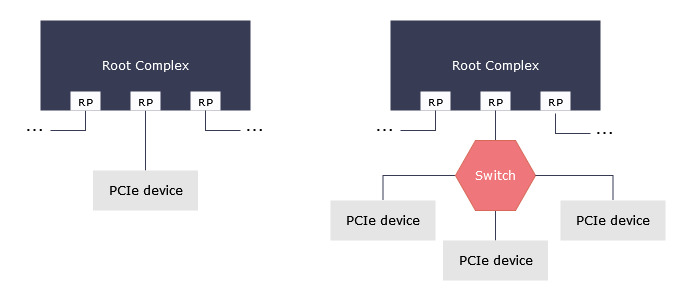
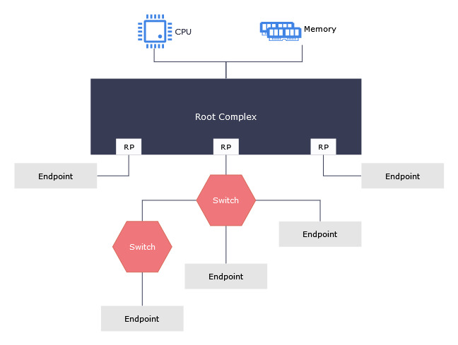
We distinguish three types of PCI Express devices: peripherals (referred to as Endpoints), switches and Root Ports (RP). The latter are physical connections on the topmost component of the PCI Express hierarchy, Root Complex, to which all devices are connected, either directly or through switches. Root Complex connects the tree of PCI Express devices to the CPU and main memory. It also acts as a switch to pass data between devices connected to different Root Ports. Conceptually, we can think of the PCI Express topology as a tree of device nodes connected by physical Links, with Endpoints as leaves:
PCI Express is a packet-based protocol. This means that data is transferred in chunks of a known size, with clearly defined boundaries. Thanks to its structured format, it is easier for devices to check data integrity during the transfer, than it would be with a simple stream of bytes. Packets are exchanged as a part of a transaction, which is established to transfer information or data between devices. It starts with a Request, and, depending on the type of Request, ends with the receipt of a Completion, or a timeout. There are four types of Requests, with the first three expecting to see Completions: Memory Read/Write, I/O Address Read/Write, Configuration Read/Write and Messages. The latter are used as in-band communication of events, including errors.
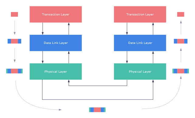
Conceptually, the PCI Express architecture is split into three layers: the Transaction layer, the Data Link layer and the Physical layer. Each layer facilitates transactions in a specific way:
- Transaction layer: the top layer responsible for constructing and processing TLPs (Transaction Layer Packets). This layer manages transactions, packet ordering and controls the data flow.
- Data Link layer: the middle layer responsible for checking the integrity of TLPs, detecting errors and correcting them.
- Physical layer: the bottom layer which encompasses circuity needed for PCI Express to operate. It is responsible for the Link initialization and maintenance, bytes encoding and power management.
The core of a packet is first created in the Transaction layer. It consists of a header that describes the packet, and depending on its type, might be followed by more data. Later, the payload travels through the other two layers, and is extended with additional information used when transforming the packet from one representation to another. The complete packet arrives at the Link, goes through and arrives at the target device. From there, the process happens again but in reverse—the packet goes up from the Physical layer and reaches the Transaction layer, with extra information peeled away at each stage, before the device receives it:
Error reporting in PCI Express — the AER mechanism
When a packet travels through the links and intermediary devices, it can get corrupted or be redirected to the wrong path. PCI Express devices have to observe what is happening on the interface and signal issues when they appear. Depending on which layer an error was discovered, it can be detected by the Requester (a device that sent a Request), the Completer (a device that responds to the Request) or a device that transmits the packet. Errors of the Physical and Data Link layers can be detected by any of them, but the Transaction layer errors are reported only by the Requester or the Completer. What’s more, some transaction level errors, such as transaction timeouts, are detected by the Requester, but in general it’s on the Completer to signal such issues.
The PCI Express errors vary in severity. The protocol classifies them into two categories:
- Correctable: hardware can recover from these errors on its own and no data is lost. They have a performance impact, especially if they happen frequently.
- Uncorrectable: data gets corrupted, and hardware cannot correct it. This kind of error requires software intervention or platform-specific handling. We further distinguish two types of Uncorrectable errors:
- Non-fatal: a particular transaction is unreliable, but the Link is functional and can be used to obtain more information about the problem
- Fatal: hardware is unreliable, and a reset is required
Once an error is detected, it can be communicated in three ways: – by sending a Completion with a non-successful state set, – marking the packet as poisoned, – generating a Message.
Advanced Error Reporting (AER) uses error Messages, and sends them to the Root Complex, which, in turn, signals them to the system. This mechanism is an optional capability of PCI Express devices. It uses a set of special registers to record the type of the error, a device that detected it (the source), and, in the case of Uncorrectable errors, saves a header of the packet that caused the failure. With basic error reporting, we don’t know this much; we can only say if an error was corrected or not. We can’t tell if Completion Timeout and Unsupported Request happened, but only that it was a Non-fatal Uncorrectable Error. On top of reporting errors in extensive detail, AER allows programming of errors’ severity. Device drivers can ask AER to treat some Non-Fatal Uncorrectable errors as Fatal or vice versa, or mask them completely.
To illustrate this process, let’s walk through a scenario in which one device wants to read the memory of another. That is, to perform a Memory Read.
In brief, a device creates a Request, it gets routed to the target, the other device acknowledges that, responds with a Completion with data, which is sent to the initiator of the process. If we take a closer look, we realize that there are many more steps that go into transferring a packet and making sure it’s intact. This also means many places where the transaction can fail.
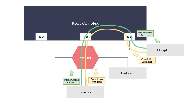
An operation shown in Figure 4 happens in the following order:
- Requester device asks the Transaction layer to create a Request.
- Transaction layer builds a Memory Read Request packet and sends it to the Data Link layer.
- Data Link layer calculates LCRC (Link CRC) of the packet and appends it to the payload coming from the Transaction layer.
- Packet is sent to the Link and goes to the switch.
- Switch routes the Request through the Root Complex; the packet eventually reaches the Completer.
- The Completer performs a few checks of the packet, e.g., if it adheres to the specified format and calculates its LCRC.
- After passing all the checks, the Completer fetches data needed to create a Completion.
- Transaction layer builds a packet with data and sends it back to the Requester (steps 1-5 in reverse).
- Requester receives the Completion, performs required checks and processes the data it retrieved.
But what if the Requester detects a corruption in the packet? Starting from the point where the packet arrives at the Requester’s Link:
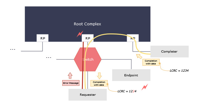
- Physical layer of the Requester passes the packet to the Data Link layer.
- Data Link layer unpacks the Completion, saves the Link CRC value.
- The device calculates LCRC and compares with the saved value; they don’t match.
- Receiver views this as an error state (Bad TLP Correctable Error) and does the following:
- Sets Correctable Error Detected bit in the Device Status register
- Populates the Correctable Error Status register
- Generates a Correctable Error Message and sends it to the Root Port
- The Root Port receives a message and generates an interrupt.
AER in the Linux kernel
Once a Root Port generates an interrupt, it’s on the software to handle the error—to report it and, in the case of Uncorrectable Errors, to perform recovery. Linux kernel provides this functionality via the AER driver (aer.ko), which responds to the interrupts, processes the error messages it received and records them in the system logs. When the module is loaded, it registers an interrupt service routine (aer_isr) that gets called when an error is detected. This routine is quite simple; it queues up error Messages and passes them to a function that processes them one by one (aer_isr_one_error). As one Message can carry both Correctable and Uncorrectable Errors, aer_isr_one_error first checks if there are any Correctable errors and logs them first. After servicing all of them, the function moves on to report Uncorrectable errors and perform recovery. The logging stage is the same for both types of errors, with an extra step for Uncorrectable errors (logging a TLP header of the faulty packet). Recovery in the Correctable case is as simple as clearing the device status register. This is more complicated for Uncorrectable errors. Depending on if this was a fatal error or not, the device driver may trigger the recovery process or simply reset the device.
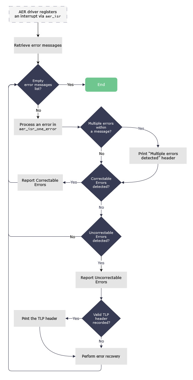
Let’s put all of what we learnt together to decipher a log produced by aer_isr_one_error for the error we discussed earlier:
$ dmesg
(...)
pcieport 0000:00:01.3: AER: Correctable error message received from 0000:03:00.0                    ①
pcieport 0000:03:00.0: PCIe Bus Error: severity=Corrected,type=Data Link Layer, (Receiver ID) ‾\__. ②
pcieport 0000:03:00.0:   device [144d:a824] error status/mask=00000040/00002000               _/
pcieport 0000:03:00.0:    [ 6] BadTLP                                                            ③
- ① says that a Root Port (
0000:00:01.3) registered an error notification from a device (0000:03:00.0). This is a message announcing that a Correctable error occurred. - ② explains the severity of an error (
Correctable) and the layer it comes from (Data Link Layer). This is followed by device and vendor IDs ([144d:a824]) and the hexadecimal view of the Correctable Error Status and Mask registers. - ③ provides a human-readable representation of the error saved in the register (
BadTLP), together with its bit index. Retrospectively, we can say that0000:03:00.0is a Requester that detected a Link CRC mismatch in the data it received on Memory Read.
These logs are pretty detailed and give a good overview of what errors are observed by the PCI Express devices. They are intended to be read by users, meaning formatted in a way that is hard for tools to consume. To aid that, the AER driver provides information on how many errors of both classes were observed in the form of sysfs entries. The error statistics can be accessed in /sys/devices/pciXXXX:YY/XXXX:YY:ZZ.W directory (XXXX:YY:ZZ is a special PCI device identifier with a Function number .W; use lspci to see the name of the device), exposed as files with aer_ prefix:
$ ls /sys/devices/pci0000\:00/0000\:00\:03.0/ | grep aer
aer_dev_correctable
aer_dev_fatal
aer_dev_nonfatal
aer_rootport_total_err_cor
aer_rootport_total_err_fatal
aer_rootport_total_err_nonfatal
aer_dev_* counters are used by all devices to record how many times they reported errors of a specific class. We have separate counters for Uncorrectable Fatal and Non-fatal errors to provide a better view of errors that require software intervention and cause data loss. aer_rootport_* stats are Root Port only and show a total number of errors that the port was notified of. The counters list all errors of a specific type, followed by the number of times they were recorded:
$ cat /sys/devices/pci0000\:00/0000\:00\:03.0/aer_dev_correctable
RxErr 0
BadTLP 1
BadDLLP 0
Rollover 0
Timeout 0
NonFatalErr 0
CorrIntErr 0
HeaderOF 0
TOTAL_ERR_COR 1
The AER driver only exposes read-only values. Users have no control over the behavior of AER and can’t change the way Non-Fatal or Fatal errors are interpreted. This requires writing directly to the PCI Express registers of the device, which is something that only some kernel mode drivers would allow.
Summary
In this post, we analyzed the PCI Express from different angles. We examined the protocol’s architecture from the I/O bus perspective, looked at its packet-based implementation and followed an example of a Memory Read transaction. In the process, we saw that the packets can get corrupted and analyzed how the PCI Express handles that. Advanced Error Reporting is a robust mechanism that informs us about the issues that happen in the PCI Express fabric and can be helpful in finding their source. Understanding the error logs that AER provides requires background which, hopefully, this article provided.
This is a lot to digest, so if there was one take-away message here, it would be that Correctable errors are not as scary as they seem. But it might be a good idea to keep an eye on them. Especially when their numbers start to spiral out of control.
References
- PCI-SIG, “PCI Express® Base Specification Revision 6.2”, January 25, 2024.
- D. Anderson, R. Budruk and T. Shanley, PCI Express System Architecture. Addison-Wesley Professional, 2004.
- R. Solomon (2014), “PCI Express® Basics & Background presentation”, PCIe Technology Seminar.
- “The PCI Express Advanced Error Reporting Driver Guide HOWTO”, Linux kernel documentation.
- AER Linux driver source code (aer_isr definition, aer_isr_one_error definition).