Proper IP address provisioning is a critical aspect of setting up any Oracle Cloud Infrastructure (OCI) environment, including OCI Kubernetes Engine (OKE). Inadequate IP allocation can lead to issues such as pods failing to spin up or worker nodes unable to scale due to IP exhaustion.
In this blog, we will explore how IP address allocations are managed in an OKE environment and provide guidance to help you design a network that meets the requirements of your OKE deployment.
Let’s examine the various OKE components that need IP addresses and determine the appropriate IP address ranges. Although these components can be placed within a single subnet, it is advisable to distribute them across different subnets. This strategy improves security and offers greater flexibility for routing decisions tailored to each component.
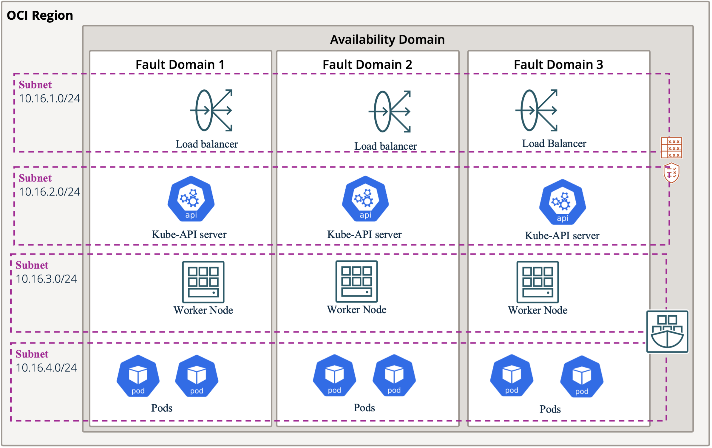
Figure 1. OKE Components
- Load Balancer subnet
- Requires the necessary number of IPs for the deployed load balancers.
- Kubernetes API Server subnet
- Requires 1 IP address.
- Worker Nodes subnet
- Needs an adequate number of IP addresses to accommodate the maximum worker nodes, based on the anticipated cluster size and scaling demands
- Pods subnet
- Requires the largest number of IPs since each pod needs a unique IP address.
- A Worker node can host up to 110 pods, depending on the node shape and the Container Network Interface (CNI) selected for the OKE cluster.
Container Network Interface (CNI) Options in OKE
The choice of CNI significantly influences the number of IP addresses required from your VCN for the OKE cluster. To begin, it’s essential to understand the different types of CNI available for an OKE cluster. These include Flannel overlay networking and VCN-native pod networking. The CNI must be selected during the cluster creation process and cannot be modified afterward.
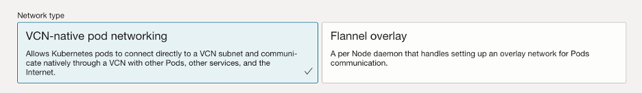
Figure 2. OKE CNI
Each CNI offers distinct capabilities, and the choice between them depends on your cluster’s specific requirements. However, for today’s discussion, we will focus solely on how IP addressing is managed in OKE. The key differences in IP allocation between the two CNIs are as follows:
- Flannel Overlay CNI: Flannel Overlay CNI creates an overlay network for pod communication, meaning that pods use virtual IPs not associated with the VCN. By default, a /16 CIDR block is allocated for internal pod communication, offering 65,536 IP addresses, though this can be customized. When pod traffic leaves a worker node, it is encapsulated with the worker node’s IP address. At the destination node, the traffic is de-encapsulated to reveal the original pod IP. For traffic going outside the cluster, the pod’s traffic is similarly encapsulated with the node’s IP, and return traffic is de-encapsulated upon re-entry.
- VCN-native CNI: With the VCN-native pod networking CNI, each pod is assigned an IP address directly from the VCN pod subnet. This approach enables pods to communicate using native VCN routing without the need for encapsulation. However, it requires careful subnet planning based on the anticipated number of pods to prevent IP exhaustion, as pod IPs are allocated from the limited address pool within the VCN.
Since Flannel overlay operates independently of VCN IP addresses and offers a large pool of IPs for pods, IP exhaustion is rarely an issue for pods. On the other hand, VCN-native pod networking CNI requires meticulous planning and subnet sizing, as each pod is assigned an IP directly from the VCN. This reliance on VCN IPs increases the potential for IP exhaustion if not managed effectively.
For the remainder of this blog, we will concentrate on VCN-native pod networking CNI and its unique considerations.
Subnets in a VCN
In any Oracle Cloud Infrastructure (OCI) environment, including Oracle Kubernetes Engine (OKE), the Virtual Cloud Network (VCN) serves as the backbone of the networking setup. When creating a VCN, you begin by selecting a large CIDR block, up to /16 (e.g., 10.1.0.0/16). Each VCN can accommodate up to five /16 CIDR blocks. For this example, we’ll use a single /16 CIDR to illustrate subnetting for the cluster.
A /16 CIDR provides 65,536 IP addresses, which can be segmented into smaller subnets to organize various components within the OKE cluster.
IP addressing consists of 32 bits, and since the maximum CIDR block size for an OCI VCN is /16, 16 bits remain available for assigning subnets and IP addresses.
These 16 bits can be distributed between subnet addresses and host IPs. Depending on the specific requirements of your environment, you can allocate more bits to either subnets or hosts, offering the flexibility to optimize IP management based on your cluster’s needs.
Subnetting Strategies for OKE: Fixed-Length vs. Variable-Length Subnet Masking (VLSM)
When assigning IPs to your OKE subnets, you can choose between two subnetting methods:
- Fixed-Length Subnetting
- Variable-Length Subnet Masking (VLSM)
Each approach offers specific advantages depending on your cluster’s needs.
Fixed-Length Subnetting
- Equal Subnet Sizes
- All subnets receive the same number of IP addresses with identical subnet masks.
- Example: Dividing a /16 CIDR block into /24 subnets results in 253 usable IP addresses per subnet.
- Simple to Plan and Manage
- Predicting and calculating IP allocation is straightforward since all subnets are uniform in size.
- This simplicity reduces management overhead in smaller networks or environments with predictable requirements.
- Less Efficient IP Utilization
- May lead to wasted IP addresses if subnets are underutilized, as each subnet receives a fixed size regardless of actual need.
VLSM
- Efficient IP Utilization
- Allows precise IP allocation, reducing waste by aligning subnet sizes with actual requirements.
- Custom Subnet Sizes
- Different components can have different subnet masks based on their specific needs.
- Increased Complexity
- Requires careful planning to prevent overlapping IP ranges, adding to the complexity of network design.”
Fixed-Length Subnetting Examples
In this section, we present two examples of fixed-length subnetting using the 10.16.0.0/16 CIDR block. The first example allocates 8 bits for subnetting and 8 bits for IP hosts, while the second example uses 7 bits for subnetting and 9 bits for hosts.
These two approaches correspond to /24 and /23 subnet masks, respectively. Each approach impacts the number of subnets, available hosts, and the scalability of OKE components.
/24 Subnet Mask:
Subnet Calculation
- /16 + 8 bits for subnetting = /24 subnet mask
Subnet List:
- 10.16.0.0/24
- 10.16.1.0/24
- 10.16.2.0/24
- …
- 10.16.255.0/24
Key Metrics:
- Number of Available Subnets: 28 = 256
- Number of Hosts per Subnet: 28 −3=253
(3 IPs are reserved for network, broadcast, and gateway addresses.)
Subnet Allocation for OKE Components
- API Server: More than sufficient IPs
- Load Balancer: More than sufficient IPs
- Worker Nodes: Can support up to 253 nodes
- Pods: Can support up to 253 pods
/23 Subnet Mask:
Subnet Calculation
- /16 + 7 bits for subnetting = /23 subnet mask
Subnet List:
- 10.16.0.0/23
- 10.16.2.0/23
- 10.16.4.0/23
- …
- 10.16.254.0/23
Key Metrics:
- Number of Available Subnets: 27 = 128
- Number of Hosts per Subnet: 29 −3=509
(3 IPs are reserved for network, broadcast, and gateway addresses.)
Subnet Allocation for OKE Components
- API Server: More than sufficient IPs
- Load Balancer: More than sufficient IPs
- Worker Nodes: Can support up to 509 Worker nodes
- Pods: Can support up to 509 pods
Variable-Length Subnet Masking (VLSM) Example
With VLSM, you can allocate subnets of varying sizes within the same VCN CIDR. This allows for more efficient use of IP space, giving smaller subnets where fewer IPs are needed and larger subnets where more hosts are required.
VLSM Example:
Let’s consider the same 10.16.0.0/16 network but apply VLSM for different components subnets. For instance:
- Pod Subnet: 10.16.0.0/22 (1022 usable IPs)
- Worker Node Subnet: 10.16.4.0/24 (253 usable IPs)
- Kube-API Subnet: 10.16.5.0/28 (13 usable IPs)
- Load Balancer Subnet: 10.16.5.16/28 (13 usable IPs)
In this scenario, larger subnets (e.g., /22) are allocated to pods that require more IP addresses, while smaller subnets (e.g., /28) are assigned to services like the Kube-API and load balancers, which have lower IP demands. This strategy optimizes IP utilization across the cluster but requires more detailed planning.
VLSM is a complex subject, and the example provided illustrates just one possible approach. It is recommended to conduct further research on VLSM to design a subnetting pattern that best suits your environment’s specific needs.
Summary
Effective IP address management is crucial for a reliable Oracle Kubernetes Engine (OKE) deployment on Oracle Cloud Infrastructure (OCI). Poor IP planning can cause pods to fail or prevent worker nodes from scaling due to IP exhaustion.
Takeaways:
- CNI Options: Flannel overlay minimizes IP exhaustion risks, while VCN-native CNI requires more precise IP planning but integrates seamlessly with VCN native routing.
- Subnetting Strategies: Fixed-length subnetting simplifies management but can lead to IP waste, whereas VLSM provides flexibility by tailoring subnet sizes to specific needs, though it is more complex to implement.