Paramount to any cloud deployment are availability and security. The shared security model conveys how a cloud service provider is responsible for managing the security of public cloud while the responsibility of security in the cloud lies with the end-customer. To assist customers in securing their workloads in Oracle Cloud Infrastructure (OCI), OCI has many security services available that can complement services from Oracle partners, such as Juniper.
This blog post guides you through configuring a resilient (active-active) pair of Juniper vSRX appliances in OCI using a combination of the network load balancer (NLB) and the dynamic routing gateway (DRG) to inspect the north-south traffic in OCI.
Network topology
The following network topology diagram shows two firewall instances, each with virtual network interface cards (VNICs)/interfaces in three subnets.
Two external NLBs accept the traffic coming in from internet. External NLB1’s public IP is registered with app1.domain.com and External NLB2’s public IP is registered with app2.domain.com. One internal NLB accepts the traffic going out to internet from within OCI.
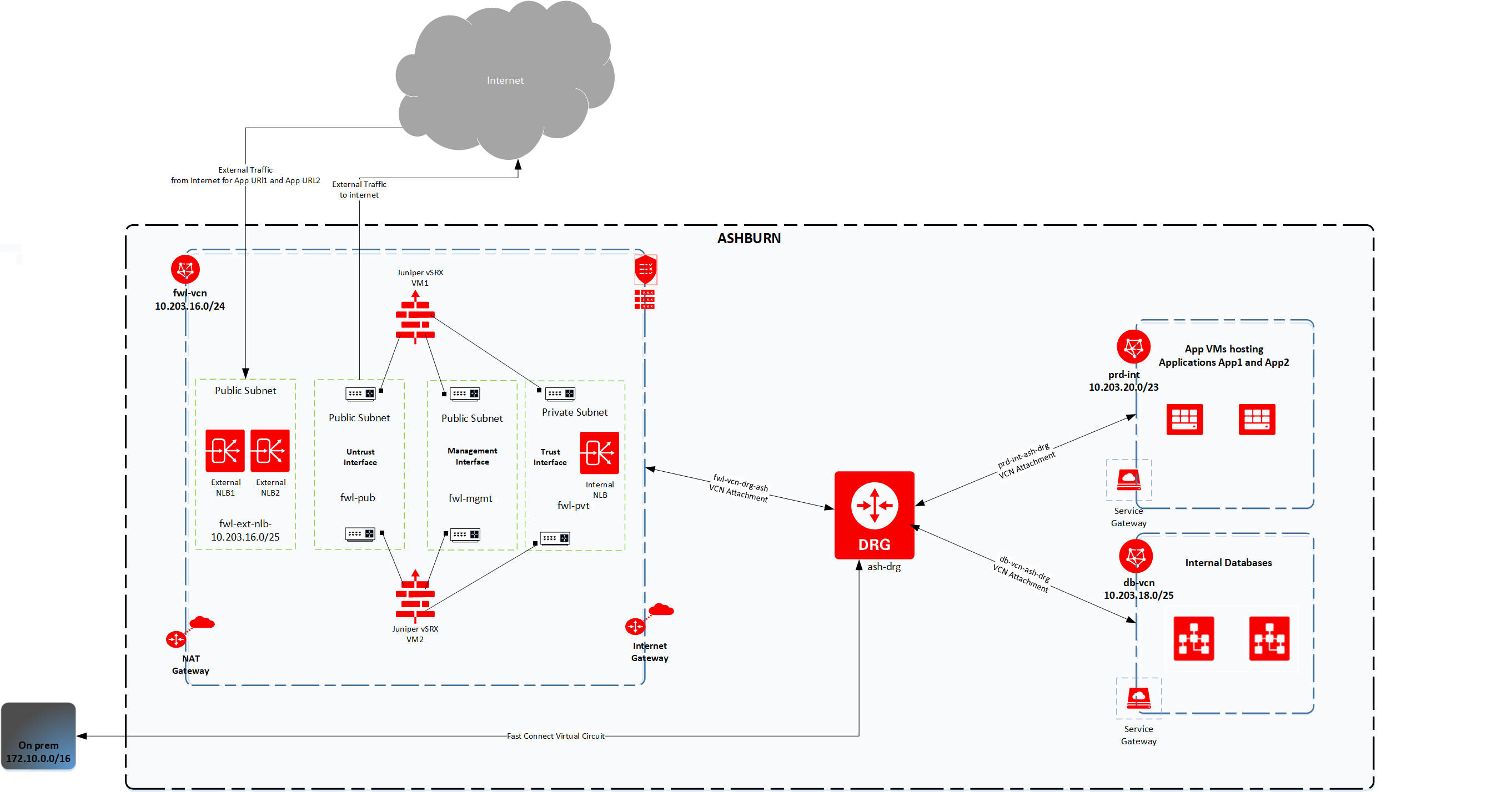
Figure 1: Network topology
The following table summarizes the network configuration used:
| OCI CIDR range | 10.203.16.0/20 |
| On-premises CIDR range | 172.10.0.0/16 |
| Juniper vSRX image version | vSRX_3.0_x86-64_20.4R2.7 |
| Firewall VM’s management interface subnet | fwl-mgmt (Public Subnet) |
| Firewall VM’s untrust interface subnet | fwl-pub (Public Subnet) |
| Firewall VM’s trust interface subnet | fwl-pvt (Private Subnet) |
| Internal NLB subnet | fwl-pvt (Private Subnet) |
| External NLB subnet | fwl-ext-nlb (Public Subnet) |
| Internal NLB private IP | 10.203.16.x |
Traffic coming in from the internet hits the external NLB, which routes it to the untrust interfaces of the firewall instances, which then sends it to the target OCI host through the DRG.
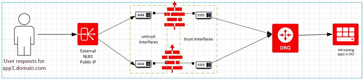
Figure 2: Traffic coming in from internet
Traffic going out to the internet from OCI hits the internal NLB (through the DRG), which routes it to the trust interfaces of firewall instances, which sends it out through the untrust interface.
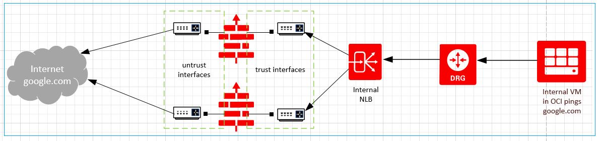
Figure 3: Traffic going out to internet
Configuration steps in OCI
-
Deploy two Compute instances using Juniper vSRX Image, selecting the management subnet for their primary VNIC. Configure two VNICs for the trust and untrust interfaces on each instance.
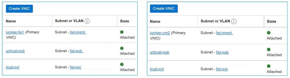
Figure 4: Firewall virtual machines (VMs) with extra VNICs for each interface
-
Create an internal, private network load balancer with backends as Juniper’s trust interfaces and a listener configuration as protocol: UDP/TCP/ICMP and port: any. We chose 2-Tuple hash as the load balancing policy to ensure maximum affinity with same backend server.

Figure 5: Internal NLB’s listener and backend set configuration -
Create an external, public network load balancer with backends as Juniper’s untrust interfaces and a listener configuration as protocol: TCP and port: any. We chose 2-Tuple hash as the load balancing policy to ensure maximum affinity with same backend server.
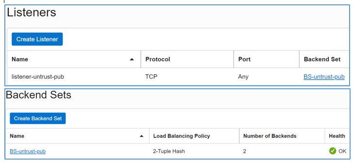
Figure 6: External NLB’s listener and backend set configuration -
Configure the OCI route tables to reflect the topology and use case.
-
DRG route table for VCN attachments: This use case shows firewall inspection only for north-south traffic so static routes are added to allow inter-VCN communication directly without passing through the firewall VCN. On-premises communication is achieved by configuring a route distribution statement. A static route rule has been added to send everything else (except specific routes for OCI VCNs and on-premises CIDRs) to the firewall VCN.
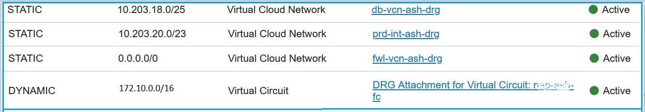
Figure 7: DRG route table attached to VCN attachments -
Configure route tables for subnets hosting internal virtual machines (VMs) to send all traffic to the DRG. The VMs can use the service gateway for YUM updates.
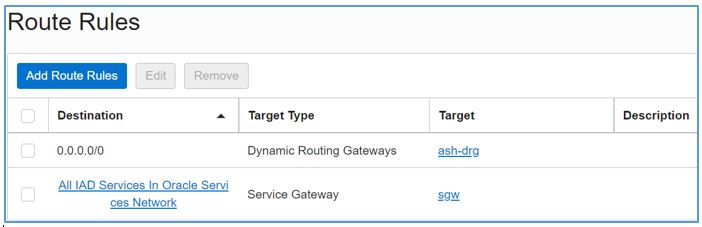
Figure 8: Route table attached to all subnets in the prd-vcn and db-vcn -
Configure the route table associated with the DRG in the firewall VCN to send all traffic to the internal NLB IP.

Figure 9: VCN route table attached to the DRG in fwl-vcn -
Configure the route table attached to the firewall’s private trust interface subnet to send traffic meant for OCI to the DRG.

Figure 10: Route Table attached to the fwl-pvt subnet -
Configure the route table attached to firewall’s public untrust interface subnet to send traffic out to internet through the internet gateway.

Figure 11: Route table attached to the fwl-pub subnet
-
-
Configure the security rules in OCI to allow traffic flow according to the topology with the following details:
-
External NLB’s security list allows traffic from internet.
-
Untrust interface subnet fwl-pub allows traffic from external NLB.
-
Internal NLB’s security list allows traffic from OCI VCNs.
-
Trust interface subnet fwl-pvt allows traffic from the internal NLB.
-
Internal OCI VMs allow traffic from firewall’s trust interface subnet.
-
Configuration steps in vSRX
-
Configure the trust and untrust interface security policies appropriately for the traffic flow.
-
For inbound internet traffic, configure sNAT to translate client’s IP address to the firewall’s trust interface IP and configure dNAT to translate public IP address of external NLB to the private IP of internal application in OCI (on that particular port, such as 80)
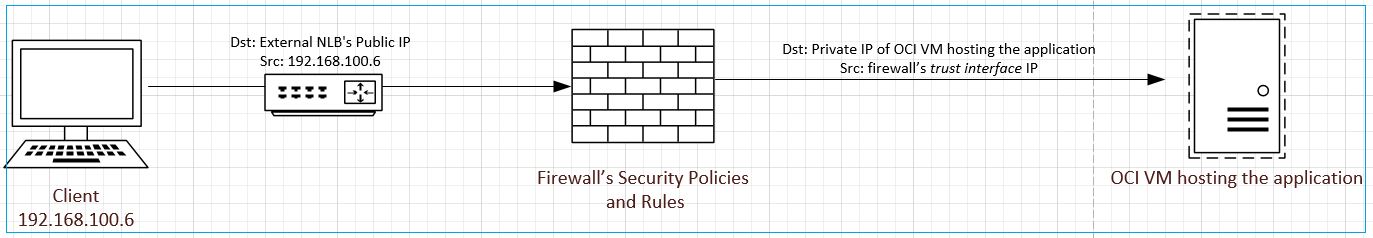
Figure 12: Firewall’s NAT policies
Validation
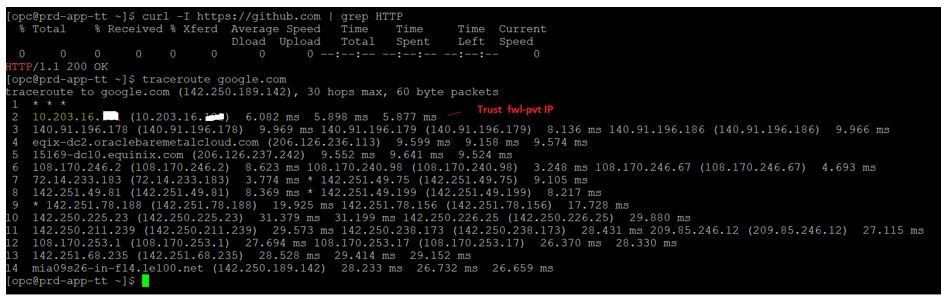
With the configurations in place, perform the following tests to verify that traffic to and from the internet moves through firewall.
For outbound traffic from internal VMs, f you ping google.com or curl github.com, the traffic passes through the firewall trust interface.
For inbound traffic, access app1.domain.com(DNS mapped to external NLB1 IP) in browser with port 80. It displays page for internal App1 deployed in OCI. Access app2.domain.com(DNS mapped to external NLB2 IP) in browser with port 80. It displays page for internal App2 deployed in OCI.
Conclusion
This blog post explained how to configure multiple Juniper vSRX appliances in Oracle Cloud Infrastructure, avoiding a single point of failure for firewalls. To learn more about OCI’s network load balancers, dynamic routing gateways, and more, see the following resources: