For decades Oracle Enterprise Manager (OEM) has been a central configuration management and governance tool for many enterprises. In this era of containerization, we’re moving our Fusion Middleware/WebLogic environments to Kubernetes. Most organizations do not run just one FMW environment: environments for different use cases, different departments and through lifecycle stages (development, test, acceptance, production). In a complex landscape of multiple databases and Fusion Middleware environments, OEM can help monitor all those targets. However, due to the architecture, OEM requires agents to have connectivity to each environment it monitors.
The blog Monitor WebLogic on Kubernetes using Oracle Enterprise Manager describes a setup to expose a WebLogic domain on Kubernetes that is managed by the WebLogic Kubernetes operator so that it can be discovered by Oracle Enterprise Manager. It suggests creating Kubernetes services of a load-balancer type for every WebLogic server. This is workable for a single domain on Kubernetes. It implies a separate service load-balancer for each WebLogic server in the domain. However, you often incur charges for each service load balancer, and each WebLogic server-load balancer pair requires a separate external IP address. Therefore, this setup may not be ideal.
To mitigate the number of load-balancer services, here are some options:
- Have an OEM Agent running in a VM in the same service network as the FMW domains. This can be done using Kubevirt, that enables running a VM in a Kubernetes environment. This is complex and resource intensive.
- Create just one load-balancer service with multiple ports and route each port to a specific WebLogic server. This is hard to manage, because of the opening and closing of ports upon creation and decommissioning of environments. This setup is complex to manage using automation code.
- Use Istio to route T3 traffic to specific WebLogic Servers from one service load-balancer. Since this is highly configurable, this is the preferred solution. But, since Istio does not know the proprietary application protocols, we need some other technology that Istio can use to route the traffic.
In our current solution, we use Istio to route HTTP traffic to the consoles and end-user applications based on host name. To do so, the Istio Ingress Gateway performs the decryption, also known as TLS off-loading. Then with HTTP traffic, Istio VirtualServices define the hostname as a matching rule. For plain TCP traffic this is not possible, Istio can only do matching on the port.
OEM uses the proprietary WebLogic t3 protocol to connect to the AdminServer to do the discovery. But Istio does not understand t3 traffic and thus cannot route it. Istio supports an extension on TLS, called Server Name Indication (SNI). With TLS, the actual traffic is encrypted (also with HTTPs), so the front-end server does not know what kind of traffic is running over the TLS tunnel. But using SNI, a client will have an interaction with the front-end server to indicate which back-end server the encrypted traffic is meant. The Front-end server can use this to choose and present the correct certificate to the client in the TLS handshake. Istio will use this to hand-over the TLS traffic to the back-end server. The consequence is that the traffic needs to be end-to-end-TLS, and only decrypted at the WebLogic server. Therefore, the WebLogic server must have its own Java Keystore with a key and certificate. Istio then can use SNI to route the traffic, regardless of what application-protocol is used.
The setup is diagrammed as:
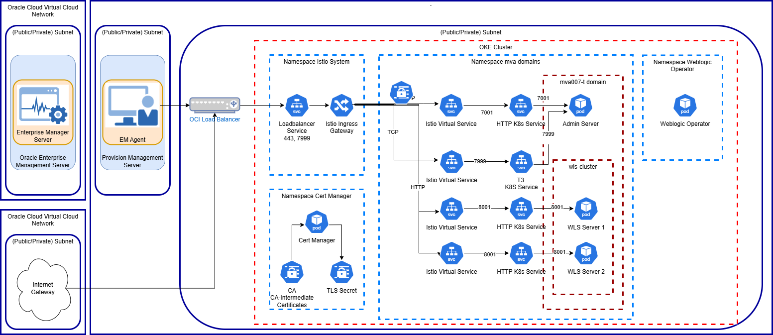
Here we have the OEM Agent running on a separate provision management server from OEM/Oracle Management Server (OMS). On Kubernetes we have Istio installed in its own namespace, where we configured an Istio Ingress Gateway with its corresponding Kubernetes load-balancer service. This communicates with the OCI service load-balancer. We also use CertManager to generate TLS keys and certificates and the domains are managed by WebLogic Kubernetes Operator. The image above shows one domain, but this setup supports multiple domains that are provisioned and decommissioned on ad-hoc basis.
In the diagram, the Istio Gateway resources were omitted that configure the Istio Ingress Gateway.
Steps to Configure WebLogic and Istio to Make it Discoverable by OEM.
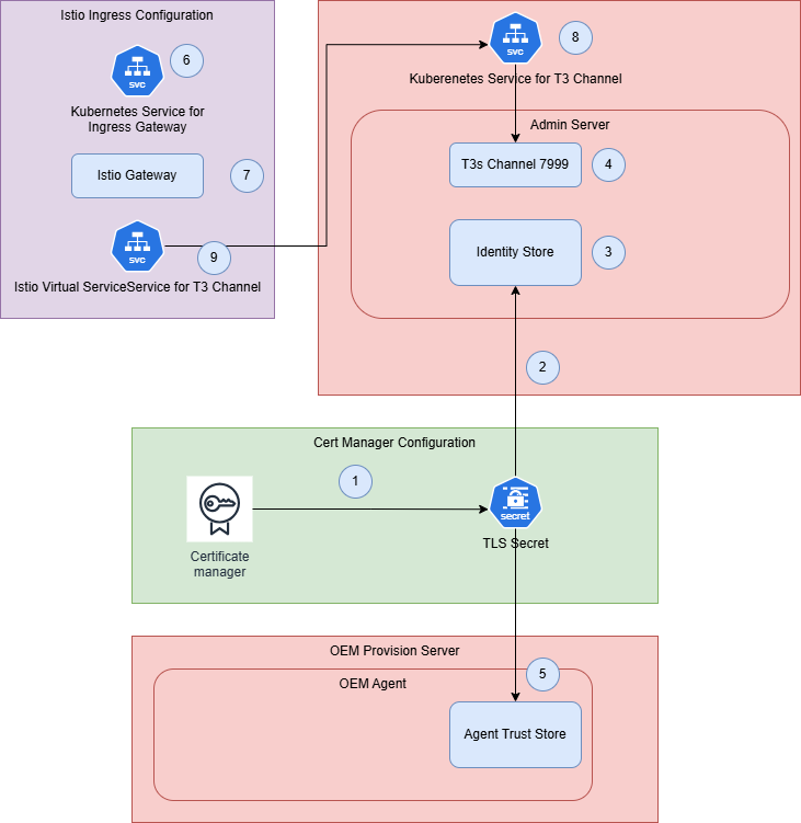
- Configure t3s on the WebLogic AdminServer
- Create a TLS certificate for the WebLogic Domain with at least the AdminServer URL of that domain (1).
- Create a JKS out of the TLS certificate and upload it to the AdminServer Pod into the domain folder (2).
- For t3s, configure the AdminServer’s Keystore to use a custom keystore and Java Trust certs. And, specify the key alias on the SSL tab (3).
- Create a t3s Channel on the AdminServer to explicitly pickup the t3s traffic (4).
- Configure OEM Agent to accept/trust custom certificates
- On the OEM agent add the CA-root/CA-Intermediate certificates (5).
- Configure Istio with TLS passthrough and SNI
- Add an extra port 7999 to the Istio Ingress Gateway to route the t3s-traffic to the WebLogic Servers (6).
- Add a separate Istio Gateway resource to define the t3s port for the different host names of the WebLogic domains (7).
- Add a Kubernetes Service for the AdminServer that exposes and routes the t3s port (8).
- Add a VirtualService per WebLogic Domain AdminServer that subscribes to the t3 traffic gateway (9).
Review the Istio configuration guidelines for TLS passthrough using SNI is described in Ingress Gateway without TLS Termination.
Configure T3 on WebLogic AdminServer
Create a separate TLS Secret for the WebLogic Domain
For SNI to work, we need to configure end-to-end TLS, and that means that a TLS key-pair for the AdminServer must be created. There are several ways to do so, you could use openssl or the Java keytool to generate one yourself. Since CertManager was implemented, it was used to generate a certificate. Apply a new CertManager certificate, defined as follows:
apiVersion: cert-manager.io/v1
kind: Certificate
metadata:
  name: tls-ora-mva009-wls-t
  namespace: ora-mva-t
spec:
  dnsNames:
  - mva009-wls-t-admin.oracle.internal
  duration: 8760h0m0s
  issuerRef:
    kind: ClusterIssuer
    name: ca-intermediate
  privateKey:
    algorithm: RSA
    encoding: PKCS1
    size: 2048
  renewBefore: 360h0m0s
  secretName: tls-ora-mva009-wls-t
  subject:
    organizations:
    - Oracle Internal
  usages:
  - server auth
  - client auth
Create a JKS based on the TLS secret
The contents of the TLS secret need to be imported into a JKS type Java Keystore. This must be done in a two-step process, where openssl creates a PKCS type .p12 file out of the secret, and the Java Keytool imports that .p12 file into a new JKS. Below is a script that supports this.
#!/bin/bash

export NS="ora-mva-t"

export WLS_DMN="mva009-wls-t"

export TLS_SECRET="tls-ora-$WLS_DMN"

export CA_NAME="ca-intermediate"

export CA_CRT=$GIT_IGNORED_DIR/ca.crt

export STORE_PWD='welcome1'

export KEY_STORE_PATH="$GIT_IGNORED_DIR/projects/ora-$WLS_DMN"

export KEY_STORE=$KEY_STORE_PATH/tls.jks

export TLS_CRT=$KEY_STORE_PATH/tls.crt

export TLS_KEY=$KEY_STORE_PATH/tls.key

export TLS_P12=$KEY_STORE_PATH/tls.p12

export KEY_NAME="mva009-wls-t-tls"


echo "Create folder $KEY_STORE_PATH"

mkdir -p $KEY_STORE_PATH

echo "Get ca.crt from $NS:$TLS_SECRET into $CA_CRT"

kubectl -n $NS get secret $TLS_SECRET -o jsonpath='{ .data.ca\.crt}' |base64 -d > $CA_CRT

echo "Get tls.key from $NS:$TLS_SECRET into $TLS_KEY"

kubectl -n $NS get secret $TLS_SECRET -o jsonpath='{ .data.tls\.key}' |base64 -d > $TLS_KEY

echo "Get tls.crt from $NS:$TLS_SECRET into $TLS_CRT"

kubectl -n $NS get secret $TLS_SECRET -o jsonpath='{ .data.tls\.crt}' |base64 -d > $TLS_CRT


rm $TLS_P12

echo "Create PKCS12 file $TLS_P12 for $TLS_CRT and key $TLS_KEY"

openssl pkcs12 -export \

               -in $TLS_CRT \

               -inkey $TLS_KEY \

               -out $TLS_P12 \

               -name $KEY_NAME \

               -CAfile $CA_CRT \

               -caname $CA_NAME \

               -password "pass:$STORE_PWD"


rm $KEY_STORE

echo "Create PKCS12 file $TLS_P12 into $KEY_STORE"

keytool -importkeystore \

        -destkeystore $KEY_STORE \

        -srckeystore $TLS_P12 \

        -srcstoretype PKCS12  \

        -srcstorepass "$STORE_PWD" \

        -deststorepass "$STORE_PWD" \

        -destkeypass "$STORE_PWD" \

        -alias $KEY_NAME

echo "List the created keystore"

keytool -list -keystore $KEY_STORE -storepass "$STORE_PWD" -v

This keystore needs to be copied to the target domain folder. In our end-solution this will be done by a Kubernetes job that creates the domain and will place the JKS-file directly in the target domain. For now, the following shows how to copy/upload the file into the existing domain folder, through the AdminServer pod.

$ export NS=ora-mva-t

$ kubectl -n $NS get pod

NAME                                             READY   STATUS      RESTARTS       AGE

mva007-osb-t-adminserver                         2/2     Running     0              14d

mva007-osb-t-osb-server1                         2/2     Running     0              14d

mva007-osb-t-osb-server2                         2/2     Running     0              14d

...

mva009-wls-t-adminserver                         2/2     Running     0              44h

mva009-wls-t-wls-server1                         2/2     Running     1 (44h ago)    44h

...

$ kubectl -n $NS cp $GIT_IGNORED_DIR/projects/ora-mva009-wls-t/tls.jks mva009-wls-t-adminserver:user_projects/domains/mva009-wls-t
This keystore needs to be copied to the target domain folder. In our end-solution this will be done by a Kubernetes job that creates the domain and will place the JKS-file directly in the target domain. For now, the following shows how to copy/upload the file into the existing domain folder, through the AdminServer pod:
$ export NS=ora-mva-t
$ kubectl -n $NS get pod
NAME                                             READY   STATUS      RESTARTS       AGE
mva007-osb-t-adminserver                         2/2     Running     0              14d
mva007-osb-t-osb-server1                         2/2     Running     0              14d
mva007-osb-t-osb-server2                         2/2     Running     0              14d
...
mva009-wls-t-adminserver                         2/2     Running     0              44h
mva009-wls-t-wls-server1                         2/2     Running     1 (44h ago)    44h
...
$ kubectl -n $NS cp $GIT_IGNORED_DIR/projects/ora-mva009-wls-t/tls.jks mva009-wls-t-adminserver:user_projects/domains/mva009-wls-t
Configure AdminServer
Having the JKS file in place, the AdminServer can be configured to use the keystore. The steps below show how to do it in the conventional WebLogic Console. In 14.1.2 you need to do it in the Remote console, in the Fusion Middleware control, using the WebLogic REST APIs, or good old WLST. For samples on the WebLogic REST APIs and WLST see the article T3 RMI Communication for WebLogic Server Running on Kubernetes.
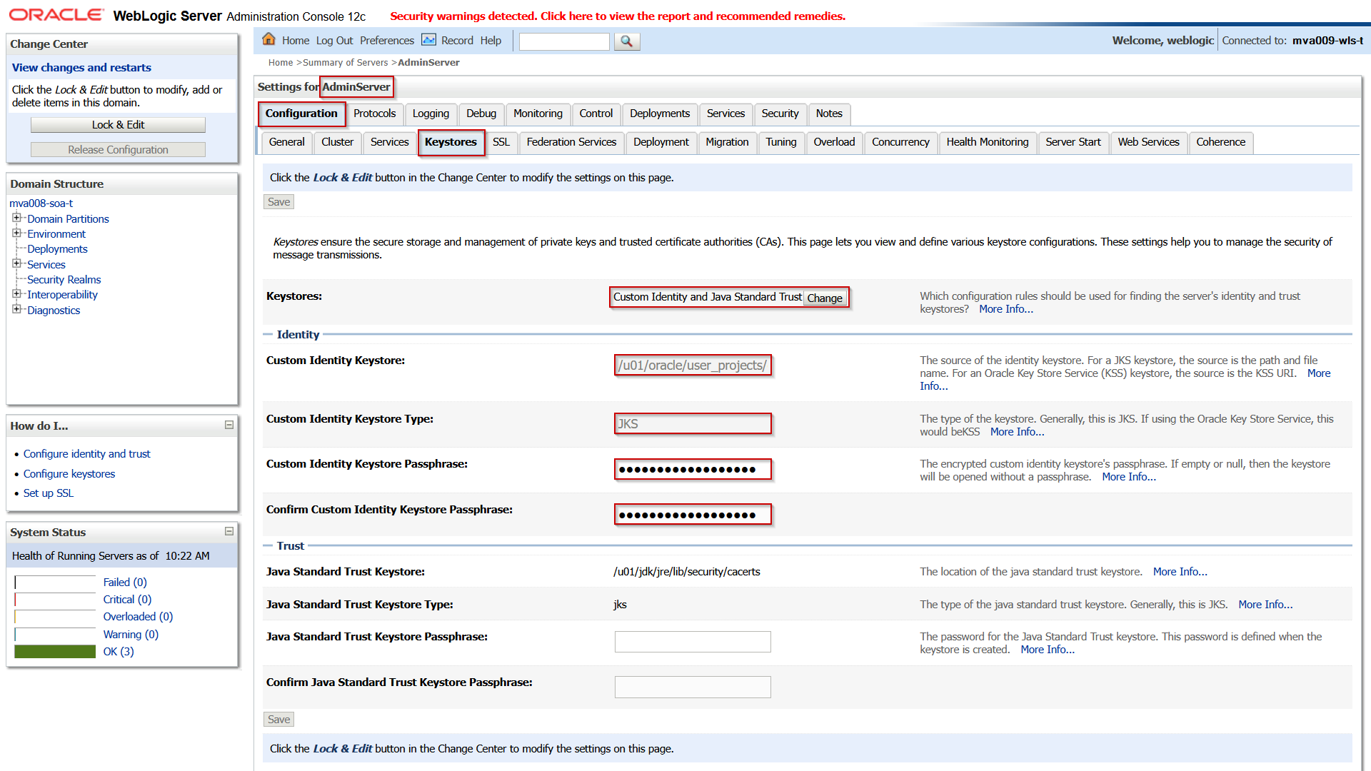
Connect to the domain, navigate to the AdminServer, and open the Keystores tab.
Set the following attributes:
| Attribute |
(Example) Value |
Comment |
| Keystores |
Custom Identity and Java Standard Trust |
Only a custom JKS for the identity is used in this setup. |
| Custom Identity Keystore
|
/u01/oracle/user_projects/domains/mva009-osb-t/tls.jks |
|
| (Confirm) Custom Identity Keystore Passphrase |
welcome1 |
This is the password of the JKS itself. Often it is the same as the passphrase of the key in the keystore. |
Save the changes and then open the SSL tab and set the following attributes:
| Attribute |
(Example) Value |
Comment |
| Identity and Trust Locations |
|
Don’t change. |
| Private Key Location
|
|
Don’t change. |
| Private Key Alias
|
mva009-wls-t-tls
|
Make sure it is the same as defined in the JKS. |
| (Confirm) Private Key Passphrase |
welcome1 |
This is the password of the Key. Often it is the same as the passphrase of the keystore. |
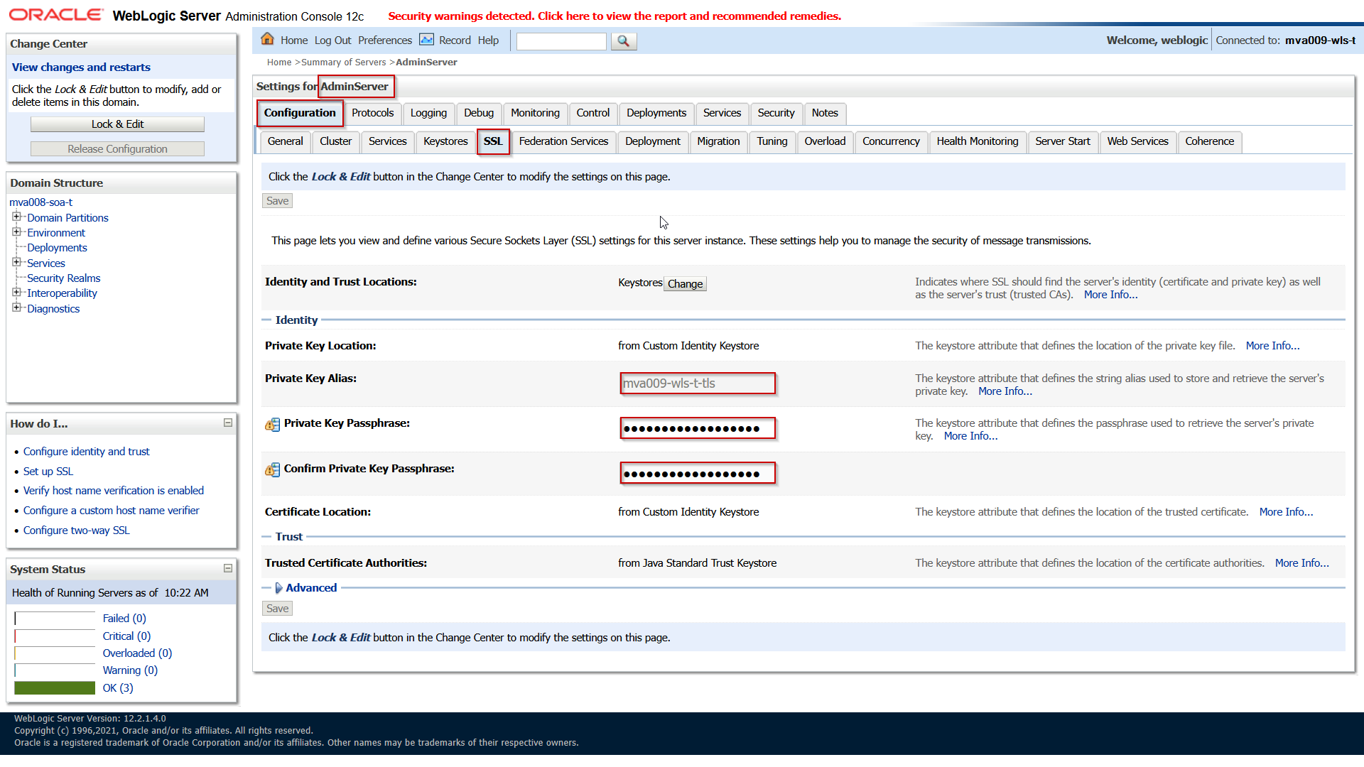
Save and activate the changes.
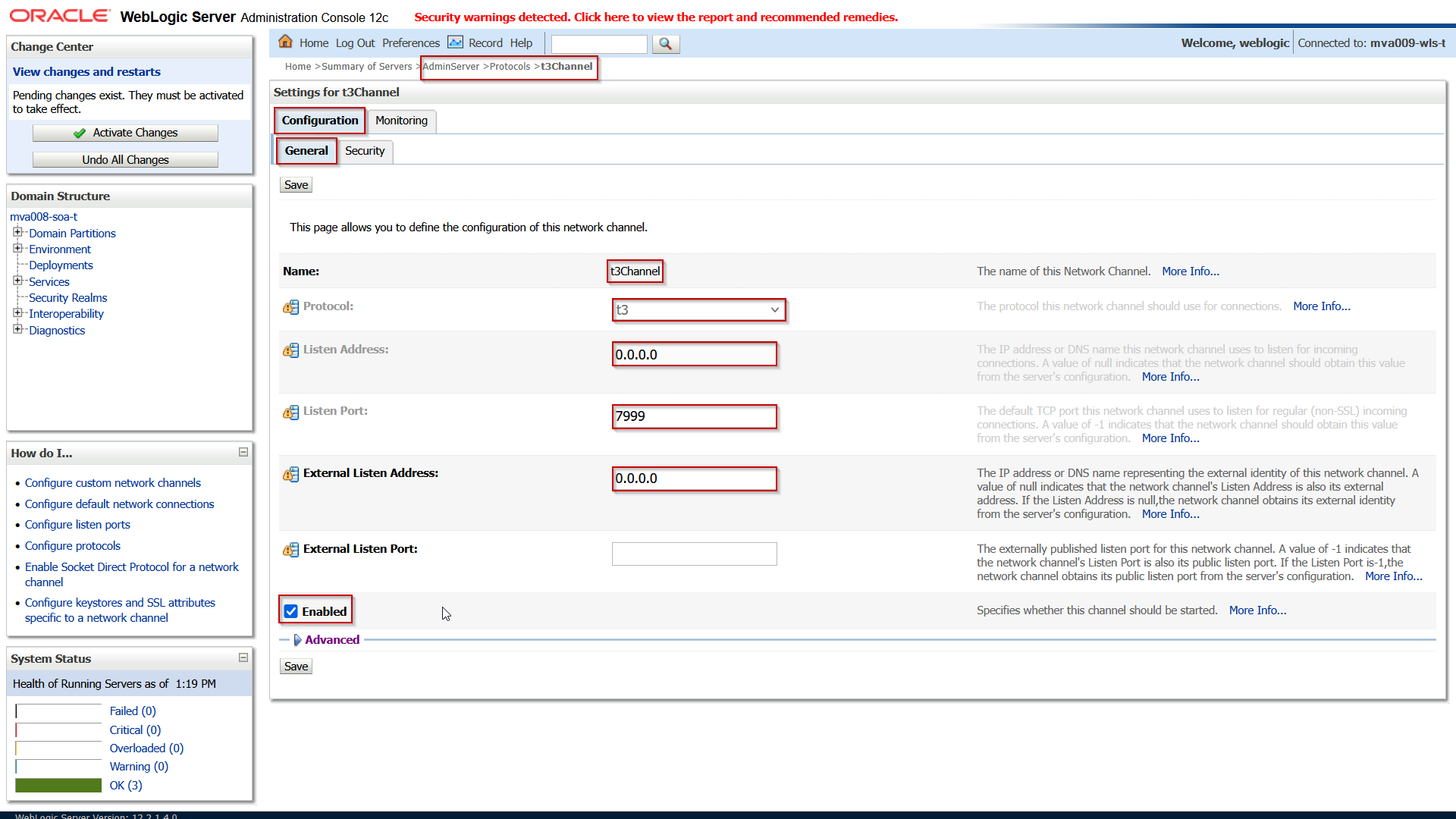
When the keystore and SSL settings are done, the road is open to define a new channel for the t3s traffic. Open the tab Protocols and subtab Channels:

Unfortunately, in 14.1.2 Fusion Middleware Control only has a view pane for custom channels. You would need to use the other options to implement this.
Click on New and fill in the following properties:
| Attribute |
(Example) Value |
Comment |
| Protocol |
t3s |
|
| Listen Address |
0.0.0.0 |
Don’t leave empty but explicitly specify this IP to listen to all addresses. |
| Listen Port |
7999 |
|
| External Listen Address |
0.0.0.0 |
When editing an existing channel this may be emptied when it is the same as the Listen Address. |
| External Listen Port |
7999 |
When editing an existing channel this may be emptied when it is the same as the Listen Port. |
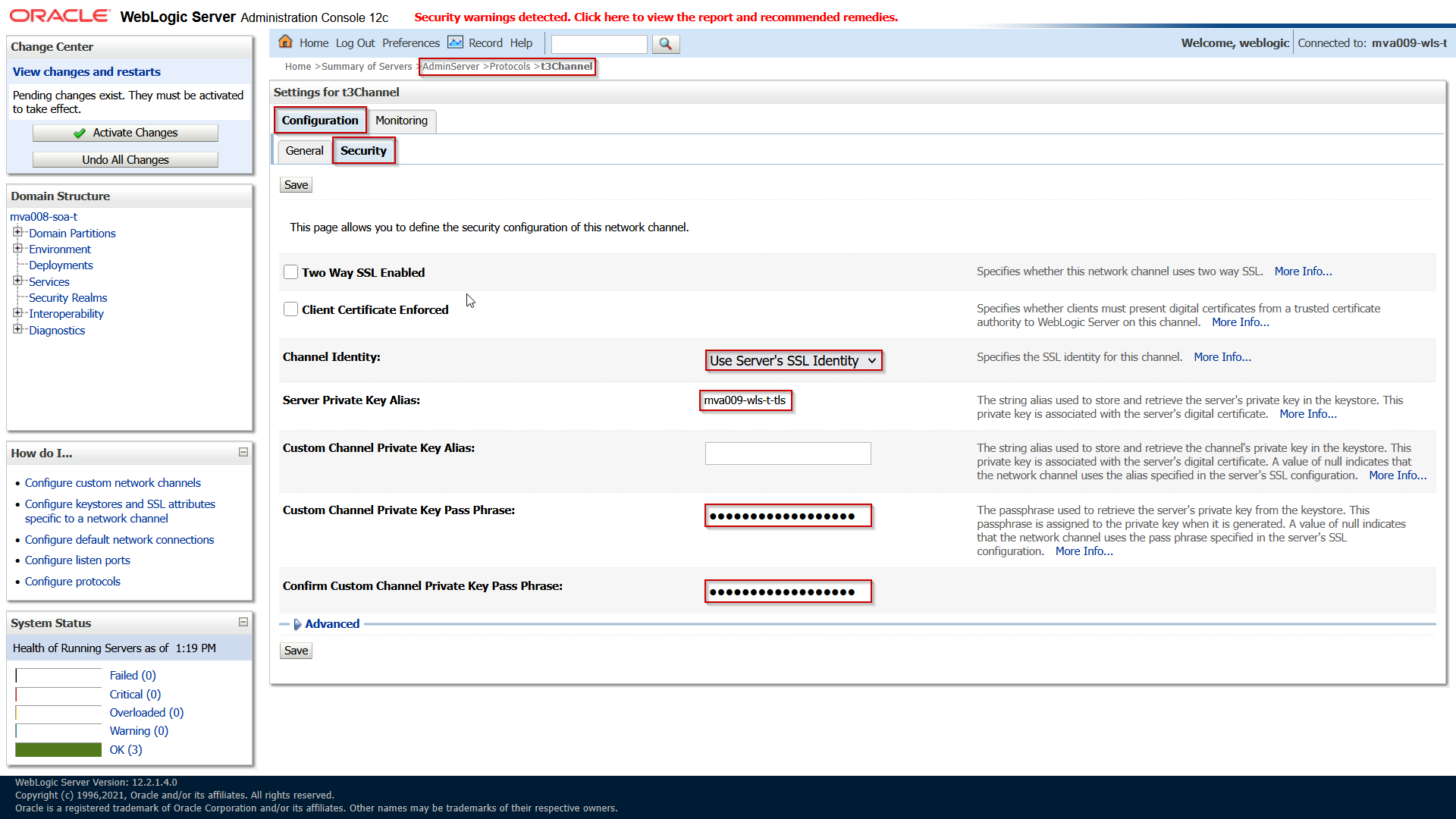
Save the changes and then open the Security subtab enter the following attributes:
| Attribute |
(Example) Value |
Comment |
| Two Way SSL Enabled |
|
Leave unchecked. |
| Client Certificate Enforced |
|
Leave unchecked. |
| Channel Identity |
Use Server’s SSL Identity |
Validate that it is set to this value. |
| Server Private Key Alias |
|
Validate that it is a read-only representation of the Private Key Alias of the SSL tab as described above. |
| Custom Channel Private Key Alias |
|
Leave empty: it is set by using the Channel Identity setting. |
| (Confirm) Custom Channel Private Key Pass Phrase |
|
This should also be defined by the Channel Identity setting. |
Save and activate the changes.
This concludes the AdminServer configuration. This can be repeated for the other clustered WebLogic Managed Servers if you want to expose them in a same way.
Add the CA and CA-intermediate Certificates to OEM Agent’s Trust
The CertManager signed the certificate using a Certificate Authority. If this is done using a custom (not public) set of self generated CA certificates, then the OEM Agent might not have these in it’s trust store. So, you may need to add them. This is described in OEM 13c Configure agent to monitor WebLogic Servers secured with custom certificate.
Get the CA and CA-Intermediate certificate PEM files and add them to a file on the provision server where the Agent is running.
Assuming that the certificates are in the oemagent’s .ssh folder as ca.crt and cai.crt, connect to the On provision management server, under user oemagent:
$ export OEM_AGENT_BASE=/u01/app/oemagent/product/agent13c

$ export AGENT_INSTANCE=$OEM_AGENT_BASE/agent_inst

$ export AGENT_HOME=$OEM_AGENT_BASE/agent_13.5.0.0.0

$ $AGENT_INSTANCE/bin/emctl stop agent

$ $AGENT_INSTANCE/bin/emctl secure add_trust_cert_to_jks -password welcome -alias ca-intermediate -trust_certs_loc ~/.ssh/cai.crt

$ $AGENT_HOME/jdk/bin/keytool -list -alias ca-intermediate -keystore $AGENT_INSTANCE/sysman/config/montrust/AgentTrust.jks -storepass welcome -v

$ $AGENT_INSTANCE/bin/emctl secure add_trust_cert_to_jks -password welcome -alias ca-root -trust_certs_loc ~/.ssh/ca.crt

$ $AGENT_HOME/jdk/bin/keytool -list -alias ca-root -keystore $AGENT_INSTANCE/sysman/config/montrust/AgentTrust.jks -storepass welcome -v

$ $AGENT_INSTANCE/bin/emctl start agent
Configure Istio with TLS Passthrough and SNI
In this phase Istio will be configured to route the t3-traffic over a separate port.
Open t3 port on Istio Ingress Gateway
First, the Istio Ingress Gateway needs to listen to an extra port. Since we use the Istio Gateway Helm chart as a sub chart (in our ArgoCD chart), the ingress gateway port list in the values.yaml must be extended with port 7999:
...
  istio-gateway:
    name: internal-ingressgateway
    service:
      type: LoadBalancer
      annotations:
        service.beta.kubernetes.io/oci-load-balancer-internal: 'true'
        oci-loadbalancer-name: your oci loadbalancer
        service.beta.kubernetes.io/oci-load-balancer-subnet1: ocid of the service loadbalander subnet
        service.beta.kubernetes.io/oci-load-balancer-security-list-management-mode: None
        oci-nsg-names: 'Custom attribute to describe the comma separated list of Network security Group names'
        oci.oraclecloud.com/oci-network-security-groups: comma separated list of Network security Group OCIDs'
        service.beta.kubernetes.io/oci-load-balancer-shape: flexible
        service.beta.kubernetes.io/oci-load-balancer-shape-flex-min: '10'
        service.beta.kubernetes.io/oci-load-balancer-shape-flex-max: '100'
      ports:
      - name: https
        port: 443
        protocol: TCP
        targetPort: 443
      - name: wls-t3
        port: 7999
        protocol: TCP
        targetPort: 7999
...
You might need to translate this to your setup of the Istio Ingress gateway. In the end the 7999 port should show up in the Kubernetes service that is created for the Ingress Gateway:
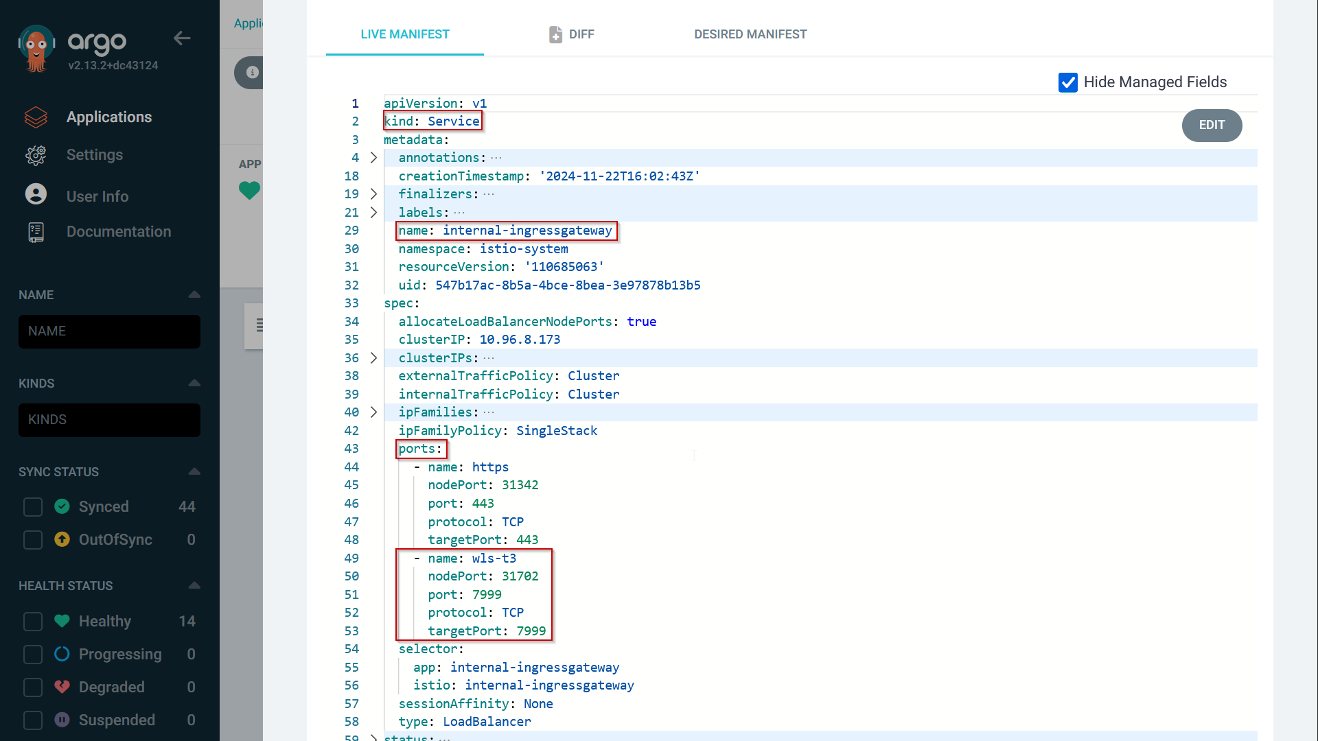
Make sure that the port is added as an ingress rule in the Network Security Group or Security list defined for the Service loadbalancer, so that it is accessible from the subnet where the OEM Agent server resides.
Istio Gateway for T3 with TLS passthrough and SNI
The Istio Ingress Gateway is configured by one or more Gateway resources. To add a configuration for the t3-traffic, apply the following definition in the istio-system namespace:
apiVersion: networking.istio.io/v1
kind: Gateway
metadata:
  name: ora-mva-t-t3-gateway
  namespace: istio-system
spec:
  selector:
    istio: internal-ingressgateway
  servers:
  - hosts:
    - mva007-osb-t-admin.oracle.internal
    - mva009-wls-t-admin.oracle.internal
    - mva013-soa-t-admin.oracle.internal
    port:
      name: ora-mva-wls-t-t3
      number: 7999
      protocol: HTTPS
    tls:
      mode: PASSTHROUGH
This gateway definition defines port 7999 for the HTTPS protocol with TLS mode PASSTHROUGH. The protocol here might be confusing since we’re not using this for HTTP(s). Istio does not allow tls.mode PASSTHROUGH for the protocol value TCP. Since the traffic is sent encrypted to the back-end server, Istio apparently does not care.
Note that this gateway resource is applied for every backend server that is exposed for the t3s-traffic. Every (new) back-end WebLogic server gets added to the list.
Istio VirtualService for SNI
Finally, the actual routing is defined in the Istio Virtual Service. In the namespace of the WebLogic domain, apply this definition:
apiVersion: networking.istio.io/v1
kind: VirtualService
metadata:
  name: mva009-wls-t-adminserver-t3-virtual-service
  namespace: ora-mva-t
spec:
  gateways:
  - istio-system/ora-mva-t-t3-gateway
  hosts:
  - mva009-wls-t-admin.oracle.internal
  tls:
  - match:
    - port: 7999
      sniHosts:
      - mva009-wls-t-admin.oracle.internal
    route:
    - destination:
        host: mva009-wls-t-adminserver-t3.ora-mva-t.svc.cluster.local
        port:
          number: 7999
This VirtualService definition connects to the Gateway resource in the istio-system namespace that we defined for the t3-traffic. Here the protocol defined is tls, that is matched on both the 7999 port and the entries in the sniHosts list, in this case mva009-wls-t-admin.oracle.internal. Then, it is routed to a separate Kubernetes service that is created for the t3 traffic. The WebLogic Kubernetes Operator creates Kubernetes secrets for the default port for every WebLogic server. Another Kubernetes service is needed to expose the t3 port. Therefore, apply the following service definition:
apiVersion: v1
kind: Service
metadata:
  labels:
    serviceType: SERVER
    weblogic.domainName: mva009-wls-t
    weblogic.domainUID: mva009-wls-t
    weblogic.serverName: AdminServer
  name: mva009-wls-t-adminserver-t3
  namespace: ora-mva-t
spec:
  ports:
  - appProtocol: tcp
    name: default
    port: 7999
    protocol: TCP
    targetPort: 7999
  selector:
    weblogic.createdByOperator: 'true'
    weblogic.domainUID: mva009-wls-t
    weblogic.serverName: AdminServer
  type: ClusterIP
Destination Rule
It is optional, but to define a TCP Keep Alive, the following destination rule can be applied:
apiVersion: networking.istio.io/v1
kind: DestinationRule
metadata:
  name: mva009-wls-t-adminserver-t3-destrule
spec:
  host: mva009-wls-t-adminserver-t3.ora-mva-t.svc.cluster.local
  trafficPolicy:
    connectionPool:
      tcp:
        maxConnections: 100
        connectTimeout: 300s
        tcpKeepalive:
          time: 7200s
          interval: 75s
Discover the FMW domain
At this point, everything is setup to have the domain discovered by OEM.
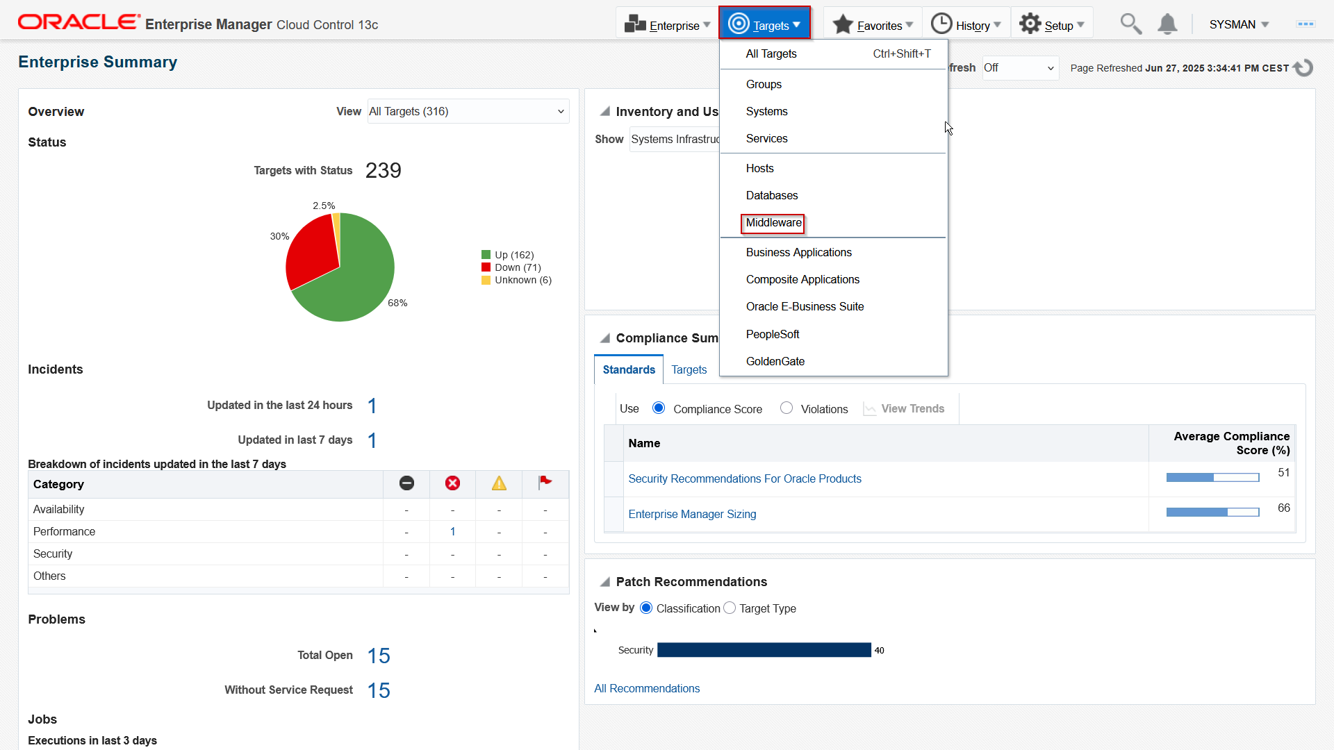
It is assumed here that the admin server address, in the example mva009-wls-t-admin.oracle.internal, is defined in the DNS, so that the OEM Agent can resolve it. Then login to OEM and navigate to the Middleware targets:
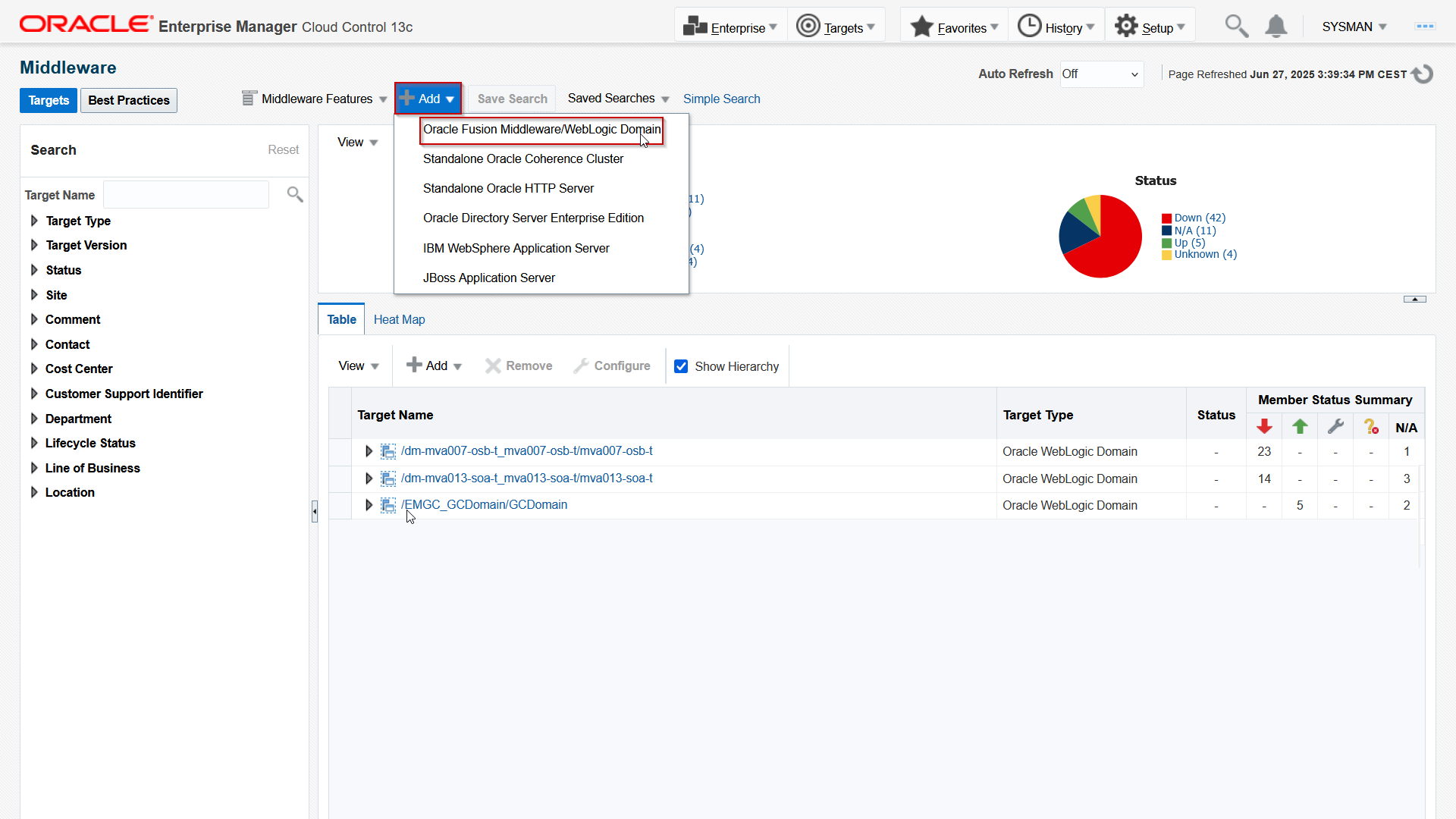
Fill in the form as follows:
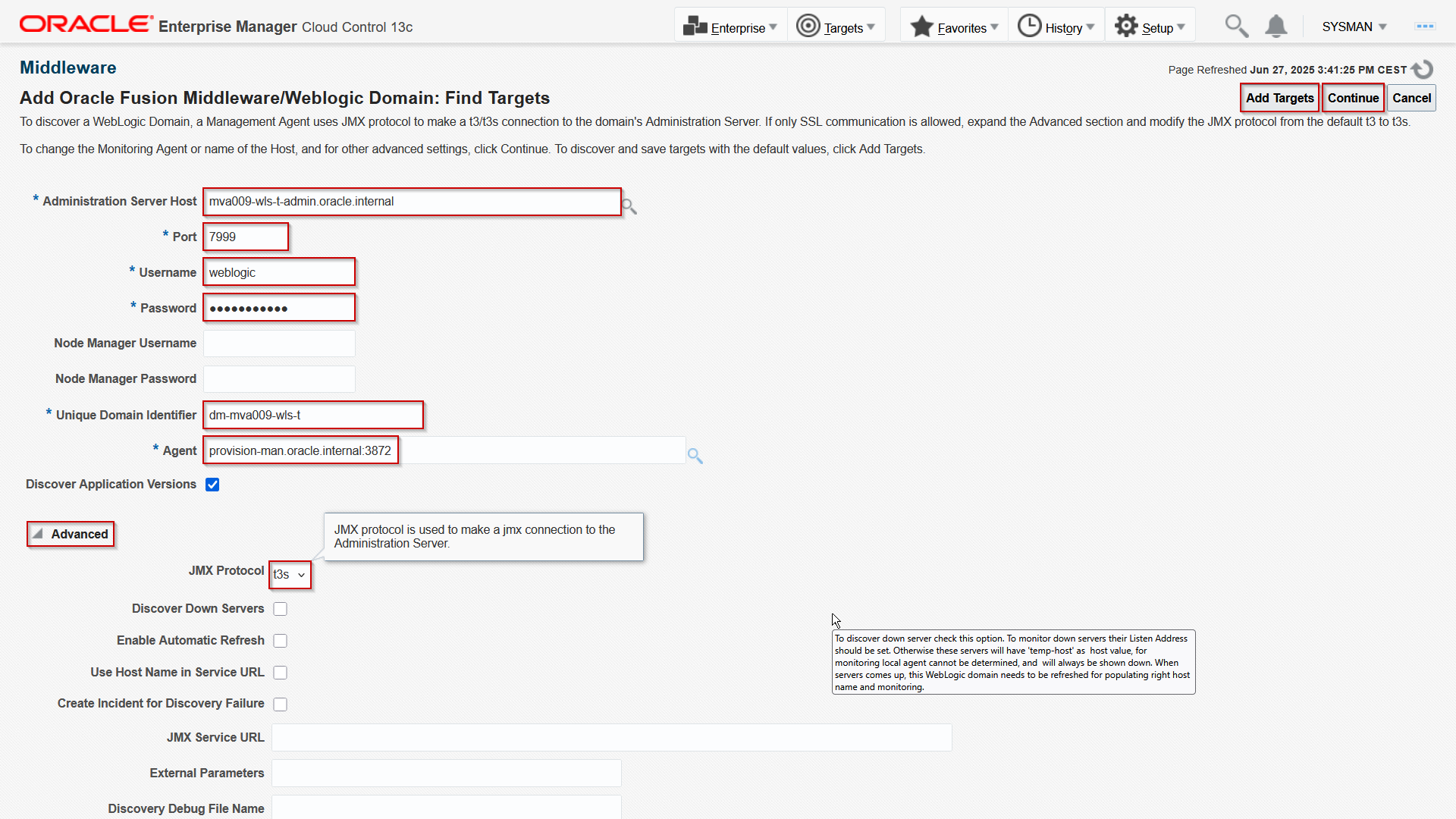
Provide the AdminServer host URL, as it is configured in Istio and put in he DNS. Provide port 7999, the WebLogic admin user credentials, and give it unique Domain identifier. Then select the provision management server where the OEM agent is running. Make sure that you set the JMX Protocol to t3s. Then click either Add Targets for direct adding or Continue and proceed with the wizard. The domain is discovered:
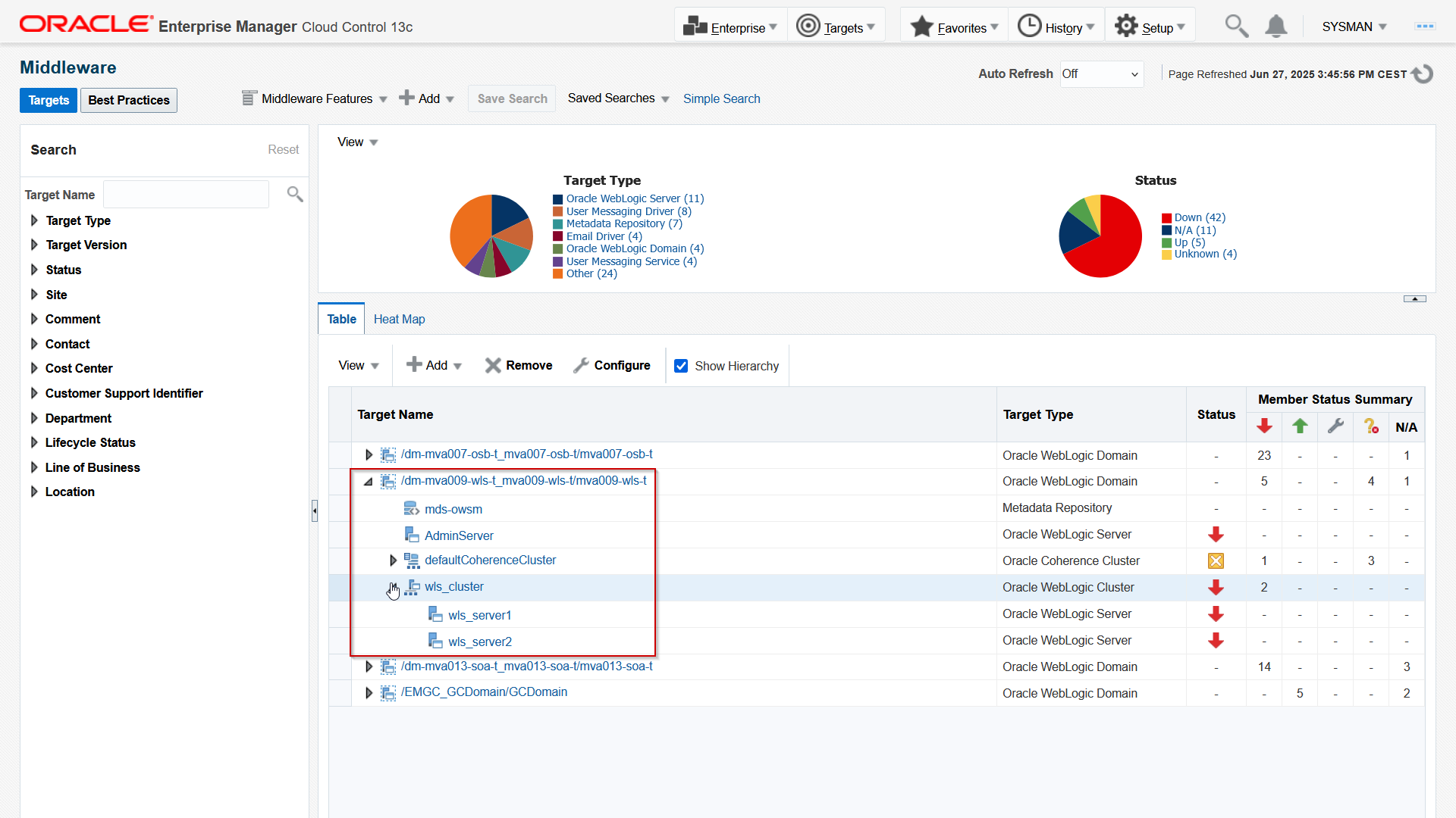
Now that the status is discoverable, you can determine how to monitor it.
In this blog, you saw how to leverage Istio and the TLS extension SNI to expose multiple WebLogic environments, specifically using the t3s protocol. The same technology can be used for JMX or other protocols, provided that the particular client supports SNI. Although not tested yet, it should be possible to connect to the AdminServer using WLST. Presumably, this technique could be used to expose development environments (OSB and/or SOASuite) for debug.
Using SNI enables the usage of end-to-end TLS for regular HTTPs traffic to expose the consoles and end-user applications. Doing so, it would allow for the definition of a certificate per domain, what would prevent affecting other domains when adding or removing a domain.
More and more customers are adopting Kubernetes solutions, both on-premises and in the cloud, both managed and self-managed. What should you with investments in existing Fusion Middleware and WebLogic platforms? When using WebLogic Kubernetes Operator, these environments run fine in a Kubernetes environment, like Oracle Kubernetes Engine. For customers who find monitoring these environments on Kubernetes too challenging, this article may help address those difficulties.
Resources
- Oracle WebLogic Kubernetes Operator is Oracle’s opensource solution to manage Fusion Middleware and WebLogic environments and is published on Github.
- Oracle provides Oracle Kubernetes Engine, a managed Kubernetes environ on both Oracle Cloud Infrastructure and Oracle Private Cloud Appliance.
- For OEM on Oracle Cloud Infrastructure, consider using the cloud management solution on the Oracle Cloud Marketplace.