Why topology matters
Modern x86 server CPUs with high core counts, like the AMD EPYC “Genoa” 96-core/192-thread processor, are not built using a single monolithic die, but instead use a hybrid multi-die (chiplet) architecture. In this design, multiple compute dies (AMD calls them Core Complex Dies, or CCDs) are connected to an I/O die via high speed interconnects. The physical layout (i.e. where a processor core lives in this hierarchy) matters because it determines cache and memory locality, which greatly influence system performance.
The Linux scheduler uses CPU and cache topology to make decisions about load balancing, task wakeups, and placement. On Genoa-class systems, the old model where all cores in a socket have uniform access to the entire L3 cache is no longer a good abstraction. Similar to NUMA for regular memory, the last-level cache (L3/LLC) is now a local resource. It is shared between cores in the same Core Complex (CCX), and crossing that boundary changes latency and effective bandwidth.
This also applies to Virtual Machines. A guest OS constructs its topology from information exposed by the VMM through interfaces like ACPI and CPUID, but it cannot directly observe on which physical CPUs the host scheduler actually runs the vCPU threads. Therefore, in order to get optimal performance from our VMs, it is not enough to request a vCPU count (e.g. -smp 380) via QEMU command line parameters. Besides how many vCPUs the guest will have, we must also describe where those vCPUs exist (sockets/dies/cores/threads) in a virtual topology that mirrors the physical layout of host CPUs where the vCPU threads will be running.
This post shows how to model an accurate EPYC “Genoa” CPU and cache topology in an x86 Linux guest using QEMU/KVM. We use QEMU’s -smp topology properties and -numa configuration to translate the physical topology levels of a Genoa server processor into a virtual topology, and basic methods to verify that the guest sees the intended configuration.
Topology concepts
There are slight differences in the terminology used to identify various CPU topology features/levels. While some are generic concepts, this blog focuses on AMD EPYC “Genoa” server design and therefore uses their naming convention and typical values in most cases. Here are some of the concepts we will discuss:
- Socket / Package: the physical CPU package in a motherboard socket i.e. a dual-socket server has 2 packages.
- Die: a block of silicon inside the package on which a functional circuit is fabricated. Modern AMD EPYC processors implement a multi-die architecture.
CCD(Core Complex Die): a compute die containing Zen cores and caches.CCX(Core Complex): group of cores sharing alast-level cache(LLC/L3). In Genoa models, aCCDcontains oneCCX, with up to eight cores and a shared 32MBL3cache. This is model-specific; in other server parts such as Bergamo/Zen4c, oneCCDcontains2CCX.
A GenoaCCX, showing 8 compute cores sharing an L3 cache:
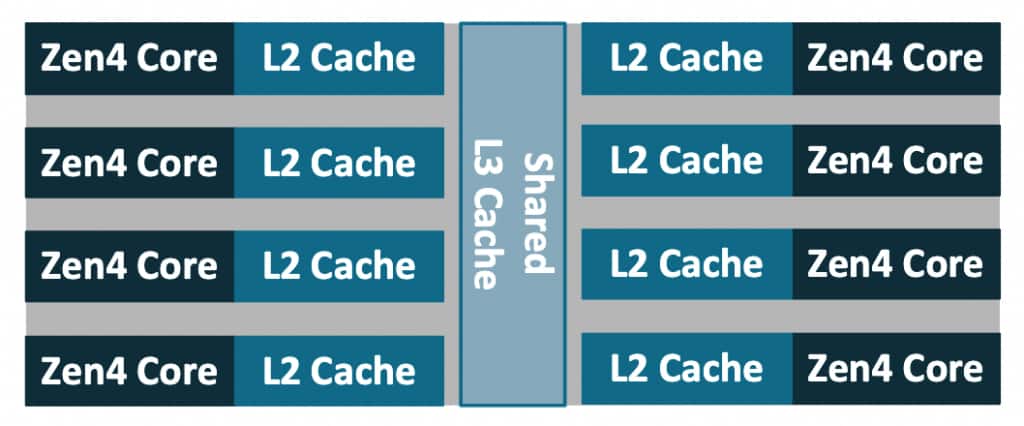
- Core: an independent execution core.
- Thread: an SMT hardware thread. The Zen 4 core supports SMT with 2 hardware threads per core.
- Logical CPU: a schedulable entity from the OS standpoint, a hardware thread. On Zen 4 with SMT enabled, there are typically two logical CPUs per core.
NPS(Nodes Per Socket): a BIOS setting which controls how many NUMA nodes the platform exposes in each socket. Divides the processor into quadrants to more finely control locality of cores, memory, and IO hub/devices. Typically configured asNPS=1, Genoa processors support values ofNPS=0,1,2,4 (some BIOSes label NPS0 as ‘Auto’).
A complete 4th Gen AMD EPYC 9004 (“Genoa”) processor package looks like:
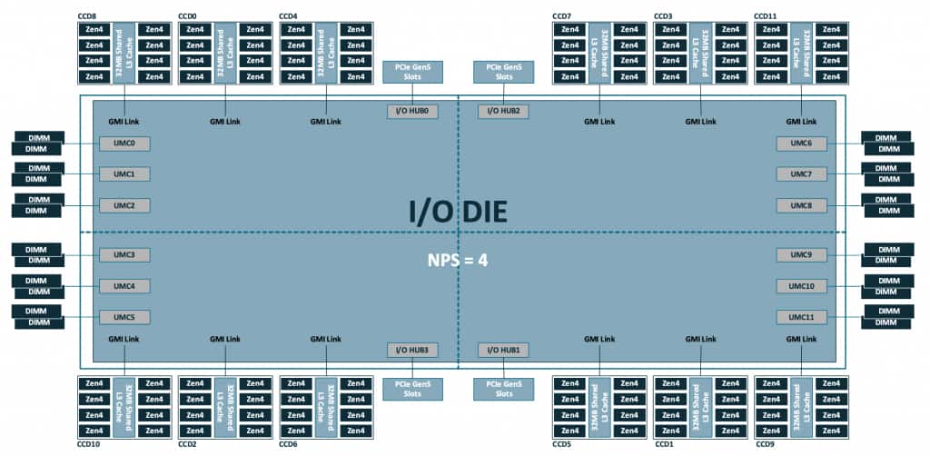
Note the 12 CCD are distributed on quadrants of the I/O die, which also holds other local resources like memory channels and PCIe lanes. In a standard configuration with NPS=1, all these resources are configured as a single NUMA node.
With these definitions in mind, let’s look at an OCI BM.Standard.E5.192 Bare Metal instance host and describe its topology. The basic lscpu output already exposes the high level organization:
$ lscpu
[...]
CPU(s):                      384
  On-line CPU(s) list:       0-383
Vendor ID:                   AuthenticAMD
  Model name:                AMD EPYC 9J14 96-Core Processor
    CPU family:              25
    Model:                   17
    Thread(s) per core:      2
    Core(s) per socket:      96
    Socket(s):               2
[...]
NUMA:
  NUMA node(s):              2
  NUMA node0 CPU(s):         0-95,192-287
  NUMA node1 CPU(s):         96-191,288-383
[...]
Combined with the architectural details listed earlier, we can describe the system as having:
- 2 sockets
- 1 NUMA node per socket
- 12
CCD/CCXper socket - 8 cores per
CCX - 2 threads per core
A single socket has:
12 CCD * 8 cores/CCD = 96 cores
96 cores * 2 threads/core = 192 logical CPUs
and a fully populated dual socket configuration doubles this quantity:
2 × 192 = 384 logical CPUsThe rest of this post explores the tools we have in QEMU to accurately describe the topology details such that a Linux guest is able to discover the intended L3 and NUMA boundaries.
QEMU: building the (virtual) CPUs
The CPU and cache topology
QEMU provides the user with a means to specify the CPU configuration via command line parameters. This is done mainly via the -smp option, although some settings are based on the -cpu model chosen. In short, -smp controls both how many vCPUs exist (typically specified via the cpus= property), as well as how the vCPUs are arranged (using sockets/dies/cores/threads).
Readers are encouraged to consult the QEMU documentation for the full description of -smp options. To reduce the scope of the discussion, this post focuses on the practical question of describing the topology of a family of AMD EPYC server processors to an x86 Linux guest using QEMU/KVM. QEMU’s -smp syntax is shared across targets, and includes topology members that are only meaningful for certain architectures or machine types. For example: drawers and books levels are useful to describe the s390x CPU topology model, but they are not necessary to describe current x86 CPU designs. For the purposes of this entry, we use the following subset of the available properties:
-smp [[cpus=]n][,maxcpus=maxcpus][,sockets=sockets][,dies=dies][,cores=cores][,threads=threads]The above topology parameters: sockets, dies, cores, and threads are ordered from “coarse” to more finely grained, and they describe a hierarchy where each higher level is a container of the level below i.e. dies=X describes X dies per socket, cores=Y means Y cores per die, and so on. The various levels do not need to be in any particular order in the command line, and values from omitted parameters will be computed based on the existing ones.
At the bare minimum, a valid invocation consists of a single value of <count> vCPUs as in: -smp 1, which as expected launches a VM with a single vCPU. On modern QEMU (since 6.2+), specifying only a vCPU count creates a “flat” topology: one socket, one thread per core, and the remaining CPUs are exposed as additional cores. Therefore a guest launched using only -smp 380 on modern x86 machine types, will show the following in lscpu:
$ lscpu
[...]
    Thread(s) per core:      1
    Core(s) per socket:      380
    Socket(s):               1
[...]
In order to accurately model the topology from the underlying hardware (or any fictional topology that we hope the guest OS will parse), we can use the topology parameters to specify the various levels. An example -smp command line to model the CPU topology for an OCI BM.Standard.E5.192 Bare Metal instance host would look like:
-smp 384,sockets=2,dies=12,cores=8,threads=2which defines a topology hierarchy matching a dual-socket Genoa system with:
- 2 sockets in the entire system
- 12 dies per socket
- 8 cores per die
- 2 threads per core
Note that -smp options describe a CPU topology, but do not directly represent other features of the design like AMD’s I/O die, memory channels, or Infinity Fabric links. Some of that information can be partially approximated by NUMA modeling (-numa) which is discussed in a later section.
Modeling L3 cache sharing domains via the dies property
As we can confirm from the -smp options documentation, QEMU doesn’t provide CCD or CCX as first-class topology level. Therefore, we need to pick a QEMU level that best represents the sharing boundary we need the guest to create. Technically the dies parameter would be more appropriately matched to the Core Complex Die (CCD) in AMD (or tiles on Intel designs). However, the level that we need to expose is the Core Complex (CCX), i.e. the one matching the “last-level cache” (L3) sharing boundary, because that is what influences scheduling decisions in the guest OS. This distinction might seem pointless for the Genoa models, since each CCD contains a single CCX, but there are other models (e.g. 97xx “Bergamo”) in which one CCD contains two CCX.
For modern x86 machine types, QEMU’s documented default cache topology model is modeled by typical CPUs i.e. L1i/L1d/L2 shared per core, L3 is shared per die. So the default behavior matches our intended use. In order to represent more complex configurations of cache sharing between CPU topology levels, recent QEMU releases (since v10.0.0) provide an smp-cache property as part of the -machine options. Using that mechanism to explicitly define the defaults for the q35 machine type:
-machine q35,accel=kvm,\
smp-cache.0.cache=l1d,smp-cache.0.topology=core,\
smp-cache.1.cache=l1i,smp-cache.1.topology=core,\
smp-cache.2.cache=l2,smp-cache.2.topology=core,\
smp-cache.3.cache=l3,smp-cache.3.topology=die \
The topology equation
You might have noticed the maxcpus property of -smp was not used in the earlier example describing a BM.Standard.E5.192 host. This property is used to specify the maximum number of vCPUs that could be enabled (e.g. via CPU hotplug), even when the guest is originally launched with a smaller count. When it is not specified, QEMU calculates it based on the values provided for the rest of the topology levels (and defaults for those omitted). The topology equation that must be satisfied is as follows:
maxcpus = sockets * dies * cores * threadsFor example, with sockets=2,dies=12,cores=8,threads=2, maxcpus must be 384. And if this is not met due to conflicting parameters, for example:
-smp cpus=72,maxcpus=80,threads=2,cores=8,dies=4,sockets=1QEMU fails to launch the guest and emits an error such as:
qemu-kvm: Invalid CPU topology: product of the hierarchy must match maxcpus: sockets (1) * dies (4) * cores (8) * threads (2) != maxcpus (80)maxcpus sets the upper bound on the number of possible vCPUs. The cpus property is used to specify the initial vCPU count, and can take any value in the [1, maxcpus] range. This allows for booting guests with potentially only a single vCPU online, and then hotplug (and/or unplug) up to maxcpus to scale as workloads demand it.
Later in this post, we will create an intentionally “incomplete” (partially populated) topology, and use vCPU hotplug to insert vCPUs at specific locations in the guest topology.
Topology extensions (topoext)
To model our guest, we use -cpu host, which means that guest CPUID is based on the actual host CPU (family/model/stepping and supported feature bits), with KVM potentially filtering some features that can’t be virtualized. Topology reporting on AMD guests is dependent on whether CPUID Fn8000_0001_ECX[TopologyExtensions] is set, which advertises support for additional leaves:
CPUID Fn8000_001D - Cache Topology Information
CPUID Fn8000_001Eh - Processor Topology Information
When we use -cpu host,+topoext to launch a QEMU guest, the topoext property advertises the Topology Extensions feature via CPUID to the guest OS. We must explicitly enable topoext, otherwise QEMU emits the following warning:
qemu-system-x86_64: warning: This family of AMD CPU doesn't support hyperthreading(2). Please configure -smp options properly or try enabling topoext feature.topoext is not enabled by default for -cpu host because it requires consistent cache topology information to be provided to avoid warnings/errors in the guest. Fortunately, this entire post is about providing an accurate topology description.
In practice, even when topoext is disabled, QEMU correctly exposes the “legacy” topology levels (sockets,cores,threads) to the guest, but fails to reflect the dies setting on the virtual topology. Since we use dies to model L3/LLC sharing domains, enabling topoext is required for the guest OS to discover those groupings.
Launching a guest with accurate topology on AMD EPYC Genoa
With all we have discussed in the previous sections, we are ready to model the EPYC Genoa host CPU on a QEMU/KVM guest. While we can recreate the exact same topology with the same vCPU count as the host’s logical CPUs, we can also use this opportunity to check how an incomplete topology will be handled by the guest OS. That is, what happens when our vCPU count is not enough to fit all the spots that are reserved in the topology.
With that in mind, since the host has a total of 384 logical CPUs, let’s reserve two cores (4 logical CPUs) and create a guest using:
sockets = 2
dies = 12
cores = 8
threads = 2
maxcpus = 384 # to match the topology equation described earlier
cpus = 380
A simplified QEMU command line would then be:
/usr/libexec/qemu-kvm \
-machine q35,accel=kvm,kernel-irqchip=split \
-cpu host,+topoext \
-smp cpus=380,maxcpus=384,sockets=2,dies=12,cores=8,threads=2 \
[...]
Using cpus=380 means only 380 vCPUs are initially present and online leaving 4 vCPU slots empty but hotpluggable at boot. The topology grid is still the full 384-slot Genoa “shape”, and Linux will discover L3/LLC boundaries consistent with dies=12,cores=8,threads=2, but it will also observe that the last CCX is not fully populated.
Validating in the guest
Finally, we can verify the Linux guest correctly recognizes the specified topology, with a special focus on the L3/LLC sharing domains, and confirming the partially populated CCX scenario described in the last section.
The most basic of checks is provided by the lscpu command:
[root@localhost ~]# lscpu
Architecture:                x86_64
  CPU op-mode(s):            32-bit, 64-bit
  Address sizes:             52 bits physical, 57 bits virtual
  Byte Order:                Little Endian
CPU(s):                      380
  On-line CPU(s) list:       0-379
Vendor ID:                   AuthenticAMD
  BIOS Vendor ID:            QEMU
  Model name:                AMD EPYC 9J14 96-Core Processor
    BIOS Model name:         pc-q35-10.2
    CPU family:              25
    Model:                   17
    Thread(s) per core:      2
    Core(s) per socket:      95
    Socket(s):               2
[...]
which confirms our initial requested vCPU count of 380 and shows that we are passing through the host CPU model. The reported Core(s) per socket: 95 reflects the 380 vCPUs populated at boot; the reserved topology is still 96 cores per socket, as defined by sockets=2,dies=12,cores=8,threads=2,maxcpus=384.
For topology details, we can consult lscpu extended options, which displays cache IDs as part of its output:
[root@localhost ~]# lscpu -e
CPU NODE SOCKET CORE L1d:L1i:L2:L3  ONLINE
  0    0      0    0 0:0:0:0           yes
  1    0      0    0 0:0:0:0           yes
  2    0      0    1 1:1:1:0           yes
  3    0      0    1 1:1:1:0           yes
  4    0      0    2 2:2:2:0           yes
  5    0      0    2 2:2:2:0           yes
  6    0      0    3 3:3:3:0           yes
  7    0      0    3 3:3:3:0           yes
  8    0      0    4 4:4:4:0           yes
  9    0      0    4 4:4:4:0           yes
 10    0      0    5 5:5:5:0           yes
 11    0      0    5 5:5:5:0           yes
 12    0      0    6 6:6:6:0           yes
 13    0      0    6 6:6:6:0           yes
 14    0      0    7 7:7:7:0           yes
 15    0      0    7 7:7:7:0           yes
 16    0      0    8 8:8:8:1           yes
 17    0      0    8 8:8:8:1           yes
 18    0      0    9 9:9:9:1           yes
 19    0      0    9 9:9:9:1           yes
 20    0      0   10 10:10:10:1        yes
[...]
As we discussed earlier, in the default cache topology model L3 is shared per die. We can see that the first 16 vCPUs (8 cores) share the same L3 index, as was requested with the cores=8 (i.e. 8 cores per die) property in the -smp command line.
Given the large vCPU count of the guest, it is easier to explore the cache sharing details using the information Linux exposes via sysfs (which is the source of data for lscpu after all). In particular, since we are interested in L3 cache, we can query the groups of vCPUs that share the same L3 cache i.e. all of the Core Complex groups existing in the system:
# cat /sys/devices/system/cpu/cpu*/cache/index3/shared_cpu_list | sort -uV | wc -l
24
Note that there are 24 CCX or L3 sharing groups on the entire system, matching our request for dies=12 * sockets=2. We can also see specific cpusets that comprise each CCX:
# cat /sys/devices/system/cpu/cpu*/cache/index3/shared_cpu_list | sort -uV
0-15
16-31
32-47
48-63
64-79
80-95
96-111
112-127
128-143
144-159
160-175
176-191
192-207
208-223
224-239
240-255
256-271
272-287
288-303
304-319
320-335
336-351
352-367
368-379
Note that all of the groups contain 16 vCPUs (8 cores), except for the last one which spans only 12 vCPUs (6 cores) [cpu368-cpu379]. This is the partially filled CCX due to cpus < maxcpus in our topology specification. Also confirming our cpus and maxcpus settings we can see that the kernel shows:
# cat /sys/devices/system/cpu/online
0-379
# cat /sys/devices/system/cpu/present
0-379
# cat /sys/devices/system/cpu/possible
0-383
online reflects the CPUs that are currently online and schedulable. In this guest it matches cpus=380. present reflects the CPUs currently present in the system. It happens to match online here, but a present CPU can also be offline. possible reflects the maximum CPU slots the kernel has allocated resources for, and can be brought online if they become present (via hotplug), which in this guest matches maxcpus=384.
The additional vCPUs can be hotplugged at the specific slots left empty in the topology. Using the QEMU monitor, we can see hotpluggable CPU devices and their socket/die/core/thread coordinates. In the output of command info hotpluggable-cpus, entries with qom_path are already present CPUs, while entries without qom_path are empty slots that can be hot-plugged. In the trimmed output below, the first entry is the next empty hotpluggable slot, and the second entry (with qom_path) is the last present and online vCPU:
QEMU 10.2.0 monitor - type 'help' for more information
(qemu) info hotpluggable-cpus
[...]
  type: "host-x86_64-cpu"
  vcpus_count: "1"
  CPUInstance Properties:
    socket-id: "1"
    die-id: "11"
    core-id: "6"
    thread-id: "0"
  type: "host-x86_64-cpu"
  vcpus_count: "1"
  qom_path: "/machine/unattached/device[380]"
  CPUInstance Properties:
    socket-id: "1"
    die-id: "11"
    core-id: "5"
    thread-id: "1"
[...]
And the next vCPU can be hot-plugged using precise topology indices:
(qemu) device_add host-x86_64-cpu,socket-id=1,die-id=11,core-id=6,thread-id=0
(qemu) [ 3798.771635] ACPI: CPU380 has been hot-added
[ 3798.806983] smpboot: Booting Node 0 Processor 380 APIC 0x1bc
which makes it available to the guest OS:
[root@localhost ~]# cat /sys/devices/system/cpu/present
0-380
[root@localhost ~]# cat /sys/devices/system/cpu/online
0-380
[root@localhost ~]# cat /sys/devices/system/cpu/cpu380/cache/index3/shared_cpu_list
368-380
After hotplug we can see present is updated, and in this guest the new CPU is also brought online. The final L3 sharing group is incrementally filled (it becomes fully populated only after all remaining vCPUs are hotplugged).
Adding -numa: matching memory locality
Another essential factor to describe locality is the NUMA information. Topology tells the guest how CPUs are grouped. NUMA tells the guest where memory is and which CPUs are local to which memory node. As with topology, mirroring the physical boundaries into the guest is crucial to guarantee optimal performance. If we query the NUMA details from the earlier guest launched with the correct topology, the NUMA information shows all resources in a single node:
NUMA:
  NUMA node(s):              1
  NUMA node0 CPU(s):         0-379
which is not the case for the host:
NUMA:
  NUMA node(s):              2
  NUMA node0 CPU(s):         0-95,192-287
  NUMA node1 CPU(s):         96-191,288-383
The BM.Standard.E5.192 Bare Metal host default configuration is to set NPS=1 in BIOS, which indicates a single NUMA node per socket. Reflecting this configuration into our guest is relatively simple with the following command line parameters:
-m 64G \
-object memory-backend-ram,id=mem0,size=32G,host-nodes=0,policy=bind \
-object memory-backend-ram,id=mem1,size=32G,host-nodes=1,policy=bind \
-numa node,nodeid=0,memdev=mem0 \
-numa node,nodeid=1,memdev=mem1 \
-numa cpu,node-id=0,socket-id=0 \
-numa cpu,node-id=1,socket-id=1 \
The relevant details to notice are:
-m 64Gsets the guest’s total RAM size (matching the sum of the two 32G backends).- Each
-object memory-backend-ram,...,host-nodes=N,policy=bindallocates a 32G chunk of guest RAM from a specific host NUMA node (host-nodes=+policy=bind). This is what makes the guest NUMA layout reflect the real host locality. - The
-numa node,...,memdev=memNlines create two guest NUMA nodes and attach each node to one of the pinned memory backends. - The
-numa cpu,node-id=...,socket-id=...lines assign vCPUs to guest NUMA nodes using topology properties: all vCPUs in socket 0 map to node 0, and socket 1 to node 1. This format ensures that assignments remain correct even if vCPU numbering changes due to hotplug or differentcpusvalues.
There are other methods of assigning vCPUs to guest NUMA nodes, including explicit vCPU ranges, but the new -numa cpu option is specifically intended for the topology driven approach we are describing in this blog entry.
This models guest NUMA node membership and host-side memory placement, but not the full latency/bandwidth relationship between nodes. There are options such as -numa dist for providing inter-node distance information, and -numa hmat-lb | -numa hmat-cache for more detailed memory topology reporting via ACPI Heterogeneous Memory Attribute Table (HMAT) entries that are out of scope for this discussion.
When using the above -numa settings, we can observe the expected configuration on our guest:
NUMA:
  NUMA node(s):              2
  NUMA node0 CPU(s):         0-191
  NUMA node1 CPU(s):         192-379
Note that the use of -numa options does not create vCPUs or memory by itself. These parameters simply assign vCPUs created by -smp, and memory created by -m or memory backends into a NUMA topology that a guest OS can discover (typically via ACPI SRAT/SLIT).
Pinning matters: making the virtual topology boundaries real
We have discussed how to make the guest topology accurately describe the layout of the physical hardware: -smp defines sockets/dies/cores/threads, and (with +topoext) a Linux guest is able to discover L3/LLC sharing domains consistent with those boundaries. However, the correct -smp hierarchy description only changes what the guest believes; it does not guarantee that vCPU threads run on host cores/SMT siblings that match the described topology, or that guest memory is allocated on the corresponding host NUMA node. Topology description alone does not guarantee performance.
The virtual topology that we have learned how to define for the guest is fixed by QEMU at VM creation time. The topology “slot” for a specific vCPU (as identified by its vCPU index) is predetermined and fixed before the guest runs, and will not be affected by guest operations. It is generated from the sequential, contiguous vCPU index, and encoded in its APIC ID. Therefore a vCPU with index N fits only in a specific “slot” in the virtual hierarchy (socket/die/core/thread). This “slot” cannot be changed for vCPU N.
The guest will make scheduling decisions based on the topology presented to it, but it has no visibility into where the host scheduler is placing the vCPU threads at runtime. Without additional placement controls, the host scheduler is free to migrate QEMU vCPU threads across sockets and across CCX/LLC domains. The guest will still “believe” certain vCPUs share an L3 cache (and make scheduling decisions based on this fact), while in reality the host might be executing those threads in different CCX or even sockets. In such scenario, any performance benefits from topology-aware scheduling in the guest OS can disappear, and at worst performance can be significantly degraded due to the guest scheduler making the “right decisions” based on inaccurate information.
In short, we must ensure that guest L3 sharing boundaries fully align with host L3 sharing boundaries.
A basic approach is to pin each virtual CCX (16 vCPUs) to one physical CCX (16 host CPUs). We can discover the host CPU ranges that share the same L3 using sysfs as we have seen before in an earlier section:
cat /sys/devices/system/cpu/cpu*/cache/index3/shared_cpu_list | sort -uV
0-7,192-199
8-15,200-207
16-23,208-215
24-31,216-223
32-39,224-231
[...]
Note: CPU numbering may be interleaved across sockets/SMT siblings as in the example above. Always rely on shared_cpu_list rather than assuming contiguous ranges.
Each line is one host L3/LLC sharing group we can use as a pinning target for a virtual CCX.
For a limited example, let’s model a single socket, 32 vCPU VM. We can use the following -smp options:
-smp 32,sockets=1,dies=2,cores=8,threads=2This requests a virtual topology with 8 cores per die. Each virtual CCX then consists of 8 cores * 2 threads = 16 vCPUs, and the virtual topology is filled sequentially, so we want:
- vCPU 0–15 (virtual
CCX0) pinned to one hostL3group - vCPU 16–31 (virtual
CCX1) pinned to a second hostL3group (on the same host socket/NUMA node for simplicity)
The details of the available methods to implement pinning are out of scope for this post, but one basic approach is to use the QEMU Machine Protocol (QMP) command query-cpus-fast to retrieve the host thread ID (TID) for each vCPU thread, and then pin them to the intended host L3 group using the taskset command.
The CCX based alignment is of course just one of the granularities involved, and this blog entry focuses on it given the relevance of L3 i.e. last-level cache in Linux scheduling. When working with larger guests, we should also consider NUMA and socket alignment to guarantee that scheduling domains created by the guest scheduler accurately represent the underlying hardware.
Summary
Modern chiplet-based CPUs like AMD EPYC “Genoa” have non-uniform locality within a socket: groups of cores (CCX) share an LLC (L3 cache), and crossing those boundaries changes latency and effective bandwidth. Linux uses this topology information for scheduling decisions, so it is worth modeling correctly in VMs. We have shown that simply declaring “how many vCPUs” the guest has does not provide enough information. For predictable performance, the guest must also be told how those vCPUs are grouped into sockets and CCX / LLC sharing domains.
To provide such details QEMU -smp option controls not only the number of vCPUs, but also the topology hierarchy the guest sees:
sockets: packages/socketsdies: a practical level to representL3/LLCsharing groupscores,threads: cores and SMT threads
As we discussed, for Genoa-like systems, a practical mapping is to use QEMU dies parameter as the L3 sharing boundary, with cores=8,threads=2 to model an 8-core CCX with SMT enabled.
A consistent topology must satisfy the rule:
maxcpus = sockets * dies * cores * threadsUsing cpus < maxcpus lets us boot with a partially populated topology, where the last CCX will be partially filled. We can then hotplug/unplug vCPUs in the “slots”, which are uniquely identified by their indices for each topology level (e.g. socket-id=1,die-id=11,core-id=6,thread-id=0).
We also discussed how NUMA configuration options can be used to align vCPUs with NUMA nodes (via -numa cpu,...) and memory backends (via memdev objects), so the guest’s view of “local memory” matches reality.
Finally, we emphasized that exposing accurate topology using the methods discussed is still insufficient because it does not enforce placement. For optimal performance the virtual CCX boundaries must be aligned with host physical CCX. This can be accomplished by pinning vCPU threads so that each guest CCX/L3 sharing group maps directly to a host CCX/L3 sharing group, ensuring the LLC domains considered for scheduling decisions are accurately reflected.