Introduction
Windows Failover Cluster is a feature designed to provide high availability support for applications and services. It allows multiple nodes to connect to the same shared storage, where only one node actively accesses this storage at a time. If the active node fails or breaks, the workload is automatically transferred to another node. This blog describes how Failover Cluster works with the Windows VirtIO SCSI driver (used in conjunction with Oracle Linux, KVM, and QEMU), how to set up Windows Failover Cluster, and how to run validation tests.
SCSI-3 Persistent Reservations
Windows Failover Cluster requires the storage driver to support SCSI-3 Persistent Reservations, which includes two types of SCSI commands: “persistent reserve in,” which gets information about a reservation on the target, and “persistent reserve out,” which sets a reservation on the target.
Persistent Reservation Support in VirtIO SCSI Driver
The Windows VirtIO SCSI driver is implemented as a storport miniport driver, which processes SCSI I/O and sends it to a backend. The information describing a SCSI I/O operation — including SCSI-3 Persistent Reservation I/O — is stored in a SCSI_REQUEST_BLOCK (SRB) structure. SRB functions are associated with the structure based on the I/O type; for SCSI-3 Persistent Reservations, those functions are SCSIOP_PERSISTENT_RESERVE_IN and SCSIOP_PERSISTENT_RESERVE_OUT. As part of the implementation of these two functions, the VirtIO SCSI driver packs the persistent reservation I/O into a ring buffer and passes the I/O data to the SCSI backend. Note that the VirtIO Block driver does not support this functionality, so configuring the Windows Failover Cluster feature requires using the VirtIO SCSI driver for paravitualized devices in KVM.
Persistent Reservation Support in QEMU
For security reasons, Linux prevents unprivileged user mode software from issuing low-level SCSI I/O commands, which causes complications for QEMU. As a workaround, QEMU forwards these I/O commands to a privileged helper utility, qemu-pr-helper, via a Unix socket. qemu-pr-helper needs to be running in the background, and the command line used to start QEMU needs to describe the path to the Unix socket and the block device associated with the helper. Here is an example:
-object pr-manager-helper,id=helper0,path=/var/run/qemu-pr-helper.sock \
-blockdev driver=iscsi,node-name=drive2,transport=tcp,portal=10.196.242.159,target=iqn.2016-03.local.server:wsfc.sas,initiator-name=iqn.2008-11.org.linux-kvm:4c377bf7-23b1-3413-a3c1-bc9f5b32a126 \
Windows Failover Cluster System Configuration
A traditional Windows Failover Cluster configuration requires a domain controller configured with Active Directory Domain Services (ADDS) and Domain Name System (DNS). The domain controller runs separately from the cluster nodes. All of the cluster nodes should join the same domain controller, they should be running the same version of Windows Server, and they should be in the same time zone. The ADDS service running on the domain controller authenticates the Failover Cluster nodes, enabling them to access domain resources. Windows Server 2016 introduced Workgroup Cluster, an alternative configuration that doesn’t require a domain controller running ADDS; in a Workgroup Cluster, the nodes join a workgroup instead of a domain. A DNS server is, however, still required. A Workgroup Cluster can be less expensive and require fewer hardware resources than a traditional Failover Cluster without sacrificing high availability.
Windows Failover Cluster Validation
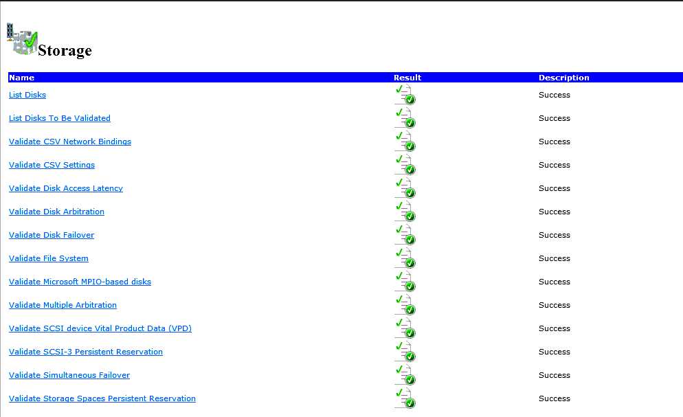
Before users create a Failover Cluster, they should validate the configuration of the nodes. Microsoft publishes detailed documents describing how to do this via a GUI (Failover Cluster Manager) or via the command line (Windows PowerShell). In brief, to use the GUI, install Failover Cluster Manager through Add Role and Features in Server Manager. Once it’s installed, select Validate Configuration in the Management field to start the validation; you will need to input the names of the nodes. A successful validation looks like this:
To validate the cluster nodes via PowerShell, run the following:
Test-Cluster –Node Server1, Server2
where you will have to supply the names of the nodes.
Windows Failover Cluster Creation
With the cluster validated, you can start the Failover Cluster via Failover Cluster Manager or a PowerShell command. To use the GUI, find the Create Cluster option under Management in Failover Cluster Manager; you will have to provide the node names at the Select Server stage of the configuration; the final confirmation page provides details of the cluster. To use PowerShell, run this command:
New-Cluster -Name cluster1 -Node node1,node2,node3,node4
where you will have to provide the cluster name and the names of the nodes.
A Windows Failover Cluster Example
Create ISCSI storage via targetcli
The storage options for Failover Cluster include Serial Attached SCSI, Fiber Channel, or iSCSI. We will work through an example of using an iSCSI storage backend in a two node Failover Cluster. On an Oracle Linux host, we will use the targetcli command to configure an iSCSI target.
First, create an image file:
/backstores/fileio/
create diskfc /public_image/wsfc/diskfc.img 10G

/backstores/fileio/diskfc> ls
o- diskfc ............................................... [/public_image/wsfc/diskfc.img (10.0GiB) write-back activated]
  o- alua ............................................................................................. [ALUA Groups: 1]
    o- default_tg_pt_gp ................................................................. [ALUA state: Active/optimized]
Create an iSCSI target and LUN:
/iscsi>
create iqn.2016-03.local.server:wsfc.sas
cd iqn.2016-03.local.server:wsfc.sas/tpg1/luns
create /backstores/fileio/diskfc

/iscsi/iqn.20...sas/tpg1/luns> ls
o- luns ...................................................................................................... [LUNs: 1]
  o- lun0 ........................................... [fileio/diskfc (/public_image/wsfc/diskfc.img) (default_tg_pt_gp)]
Set the ACLs for the iSCSI initiators associated with nodes A and B:
cd /iscsi/iqn.20...sas/tpg1/acls>
create iqn.2008-11.org.linux-kvm:4c377bf7-23b1-3413-a3c1-bc9f5b32a126    -- The initiator name is the UUID of node A
create iqn.2008-11.org.linux-kvm:4c377bf7-23b1-3413-a3c1-bc9f5b32a346    -- The initiator name is the UUID of node B
Create portals:
/iscsi/iqn.20.../tpg1/portals> create 10.196.242.159 3260

/iscsi/iqn.20...wsfc.sas/tpg1/portals>ls
o- portals ................................................................................................ [Portals: 1]
  o- 10.196.242.159:3260 .......................................................................................... [OK]
The iSCSI target layout looks like this:
o- iqn.2016-03.local.server:wsfc.sas ........................................................... [TPGs: 1]
  o- tpg1 ......................................................................... [no-gen-acls, no-auth]
    o- acls .................................................................................... [ACLs: 2]
    | o- iqn.2008-11.org.linux-kvm:4c377bf7-23b1-3413-a3c1-bc9f5b32a126 ................. [Mapped LUNs: 0]
    | o- iqn.2008-11.org.linux-kvm:4c377bf7-23b1-3413-a3c1-bc9f5b32a346 ................. [Mapped LUNs: 0]
    o- luns .................................................................................... [LUNs: 0]
    o- portals .............................................................................. [Portals: 1]
      o- 10.196.242.159:3260 ........................................................................ [OK]
The two cluster nodes need to connect the iSCSI target separately.
On node A, lsscsi shows:
[30:0:0:0] disk LIO-ORG wsfc 4.0 /dev/sdh
On node B, lsscsi shows:
[30:0:0:1] disk LIO-ORG wsfc 4.0 /dev/sdi
QEMU Command Line Options for the Nodes
The following QEMU command line options are used to describe the storage for node A:
pre class=”brush: bash;” style=”background:#eeeeee;border:1px solid #cccccc;padding:5px 10px;”>-object pr-manager-helper,id=helper0,path=/var/run/qemu-pr-helper.sock \ -device virtio-scsi-pci,id=scsi0,bus=pci.0,addr=0x4 \ -blockdev driver=raw,file.driver=host_device,cache.direct=off,cache.no-flush=on,file.filename=/dev/sdh,node-name=drive2,file.pr-manager=helper0 \ -uuid 4c377bf7-23b1-3413-a3c1-bc9f5b32a126 \ -device scsi-block,bus=scsi0.0,channel=0,scsi-id=0,lun=0,drive=drive2,id=scsi0-0-0-0 \
And these command line options are used for node B:
-object pr-manager-helper,id=helper0,path=/var/run/qemu-pr-helper.sock \
-device virtio-scsi-pci,id=scsi0,bus=pci.0,addr=0x4 \
-blockdev driver=raw,file.driver=host_device,cache.direct=off,cache.no-flush=on,file.filename=/dev/sdi,node-name=drive2,file.pr-manager=helper0 \
-uuid 4c377bf7-23b1-3413-a3c1-bc9f5b32a346 \
-device scsi-block,bus=scsi0.0,channel=0,scsi-id=0,lun=0,drive=drive2,id=scsi0-0-0-0 \
Potential Issues
QEMU releases missing an upstream fix may cause VMs to hang during Windows Failover Cluster validation testing. This happens when the QEMU command line options werror=stop,rerror=stop are provided for a drive — QEMU fails to clean up correctly after an error and/or attempts to handle an error itself instead of passing it to the guest. When this happens, the disk status shows:
drive-scsi0-0-0-0 (#block396): /dev/sdh (raw)
    Attached to:      scsi0-0-0-0
    I/O status:       failed
    Cache mode:       writeback, direct
and the VM status shows:
(qemu) info status
VM status: paused (io-error)
Oracle QEMU releases have this fixed.
Summary
The Windows VirtIO SCSI driver in combination with an Oracle Linux/KVM/QEMU virtualization stack supports Windows Failover Cluster, although the configuration details can be complex.