1)How to Build a Secure Bastion Host on Oracle Cloud Infrastructure(OCI)
If you run private workloads on OCI, a bastion host is your secure doorway in. Instead of exposing databases or app servers to the internet, you connect to a single, tightly controlled VM and hop,or tunnel, from there into your private subnets. In this walkthrough, I’ll guide you through creating a self-managed bastion on OCI Compute using the OCI Console. Along the way I’ll call out practical tips, security gotchas, and what to do after the VM is up.
What you’ll need:
– A compartment where you can create Compute, VCN(Virtual Cloud Network), subnets, and NSGs(Network Security Groups)
– A VCN with a public subnet for the bastion and private subnets for your targets
– An SSH key pair (keep the private key safe)
– IAM(Identity and Access Management) permissions to create and use networking and compute resources
Here are the step-by-step instructions to create and use an OCI Bastion for secure access to our private resources.
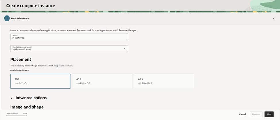
Step 1: Name and place your instance
Head to Compute > Instances > Create instance. Give it a clear name like PHXBASTION, choose the right compartment, and select an Availability Domain (AD-1, AD-2, or AD-3). For a bastion, a modest shape is enough—think VM.Standard.E4.Flex with 1–2 OCPUs—unless you expect a lot of concurrent sessions..
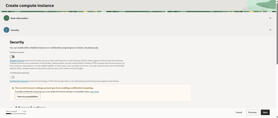
Step 2: Security options
If the shape supports it, enable Shielded instance for measured boot and extra tamper resistance. It’s a nice defense-in-depth layer. We’ll still harden the OS(Operating System) after launch , patches, minimal packages, and strict SSH settings.
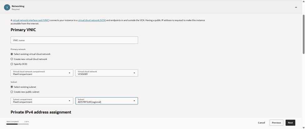
Step 3: IP address choices
Under Primary VNIC(Virtual Network Interface), pick your existing VCN and the subnet where the bastion will live. For the classic pattern, use a public subnet so you can assign a public IP. Make sure that subnet’s route table has an Internet Gateway and your NSG/security list allows inbound SSH (port 22) only from trusted corporate CIDRs. Prefer a private-only entry point? You can place the VM in a private subnet and reach it over VPN/FastConnect or use OCI’s managed Bastion service for the public front door.
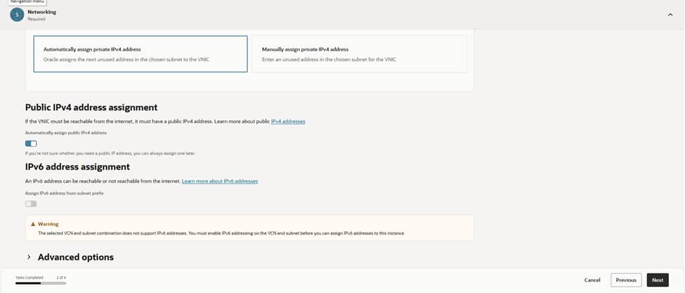
Let OCI assign the private IPv4 address automatically. If this is a public bastion, enable a public IPv4 address as well. Keep it locked down with NSGs, so only the right source IP ranges can reach port 22. If you use IPv6, make sure routing, security lists, and policies are in place before assigning it.
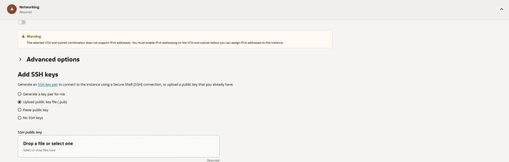
Step 4: Add your SSH keys
Upload your public key or generate a new key pair in the Console. Download the private key now as you won’t be able to retrieve it later. Do not enable password-based SSH. If you have cloud-init scripts for hardening (disabling root SSH, creating admin users, MOTD/banner), add them under Advanced options.
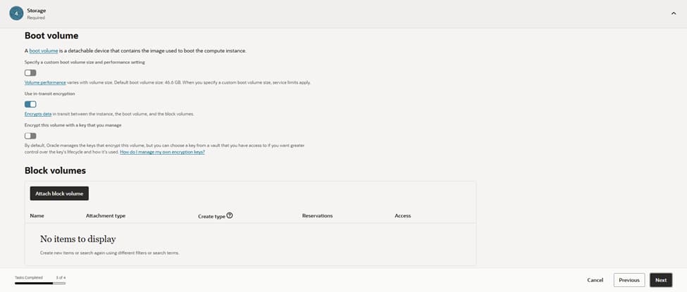
Step 5: Storage settings
Keep the default boot volume size unless you plan heavy tooling or logs on the bastion. You typically don’t need extra block volumes. Enable automated backups if your policy requires it.
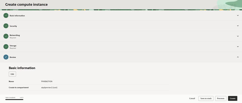
Step 6: Review and create
Double-check the name, compartment, network, and keys, then click Create. Once the instance is running, you’ll see its private IP and (if selected) public IP.
Connect and test
– From your machine: ssh -i <private_key> opc@<bastion_public_ip>
– Update the OS right away (for example, sudo dnf update -y on Oracle Linux).
– Install any required tools(MongoShell,Sqlcl,Telnet)
– Validate you can reach private targets from the bastion. Ensure those targets allow inbound traffic, from the bastion’s private IP, on the required ports.
2)CREATING ACD DATABASES ON DEDICATED INFRASTRUCTURE(PRIMARY,LOCAL STANDBY (PHX), REMOTE STANDBY(ASH)) AND CREATING AI ATP DATABASE ON PHX REGION
Here are the steps for setting up a primary database, local standby (PHX), and remote standby (ASH) on Autonomous Database Dedicated. Note: Autonomous Data Guard (ADG) is configured at the Autonomous Database level, but it requires the target infrastructure (ACD(Autonomous Container Database)/VM Cluster) to exist at each site.
Plan and prerequisites
– Regions and roles: We will set up our Primary database and local standby in us-phoenix-1 (PHX). The remote standby will be in us-ashburn-1 (ASH). Ensure IAM policies allow manage/use for Autonomous Exadata Infrastructure, Autonomous VM Clusters, ACDs, and Autonomous Databases.
– Networking: Prepare required private subnets, NSGs/security lists in both regions; confirm private access to Object Storage; set maintenance windows and tagging strategy.
– Capacity: Size Exadata shapes, OCPUs, storage, and license model consistently across sites.
Provision Autonomous Container Database
A. PHX (Primary site)
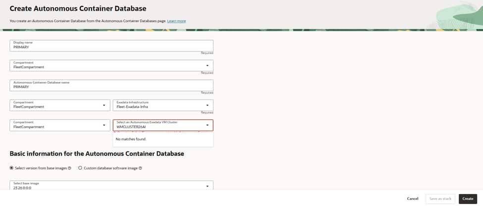
Choose a descriptive display name (for example, “PRIMARY”) and select the target compartment.
Select the Dedicated Exadata Infrastructure and the Autonomous VM Cluster that will host this ACD.
Pick the base database version (for example, 23ai). Keep versions consistent across peer ACDs that use Autonomous Data Guard.
Choose “Rolling” as the maintenance method to minimize disruption during updates.
Configure a preferred maintenance schedule that aligns with your change windows.
If you operate multiple ACDs for DR(Disaster Recovery), coordinate windows to avoid overlap.
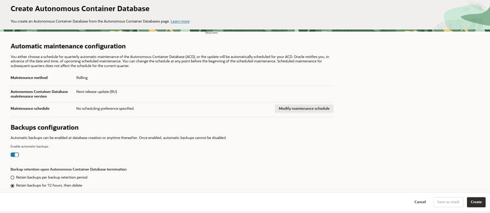
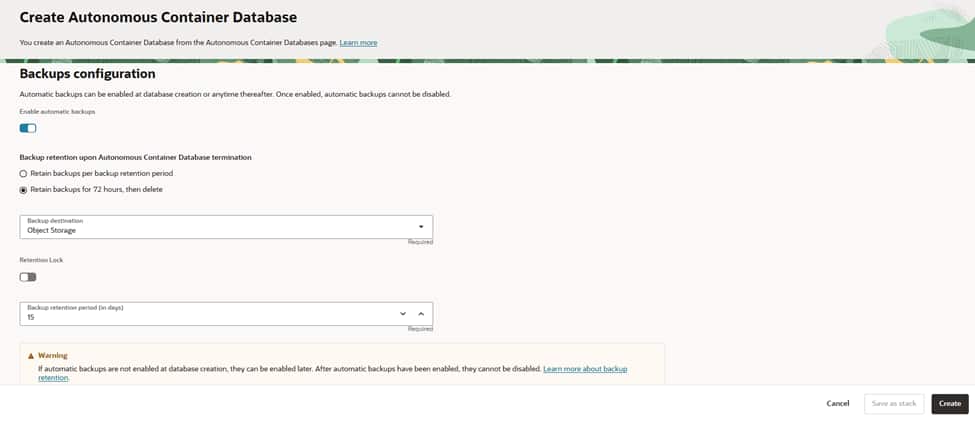
Enable automatic backups (recommended for Dedicated). Note that once enabled, they cannot be disabled later.
Select the backup destination (typically Object Storage) and ensure necessary IAM policies are in place.
Set retention: either the standard backup retention period or a shorter “retain for 72 hours, then delete.”
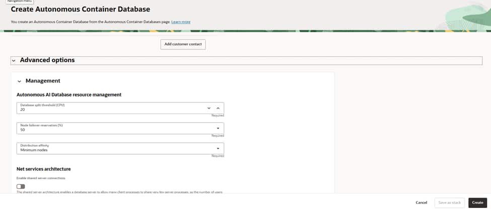
Set the database split threshold (EPT) as needed; the default suits most environments.
Reserve capacity for node failover by specifying a percentage to maintain headroom for resilience.
Choose distribution affinity (for example, Minimum nodes) to spread load for availability.
Decide whether to enable shared server connections; keep it off unless you have high‑connection, low‑CPU session profiles.
Verify the name, compartment, AVMC(Autonomous VM Container), version, maintenance, and backup settings.
Create the ACD and wait for it to reach the Available state.
B. PHX (Local standby site)
– Create a peer ACD on this second AVMC using same steps named as Local_Stby. Ensure versions/patch tracks match the primary ACD to support ADG.
C. ASH (Remote standby site)
– Create a peer ACD on this second AVMC using same steps named as Remote_Stby., matching DB version/patch track with PHX.
3) Create the primary Autonomous Database (on Dedicated)
You’ve stood up a primary Autonomous Container Database (ACD) in PHX—now let’s create an Autonomous Transaction Processing (ATP) database inside it. In this walkthrough, I’ll narrate the choices you’ll make in the Create Autonomous AI Database flow on Dedicated Exadata Infrastructure
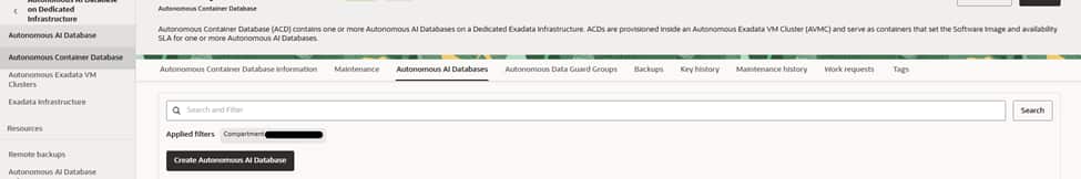
– In PHX, open the target ACD (primary) , select Autonomous AI Database tab and press “Create AI Autonomous Database” button.
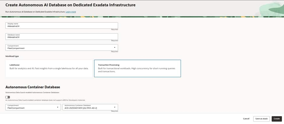
Give your database a clear, environment-aware name , in our case it is PRIMARYATP for both display name and database name. Select the compartment that owns and governs this database. Choose the workload type as Transaction Processing to use Mongo API for Oracle.
Select your primary Autonomous Container Database (ACD) in the PHX region so the new ATP inherits its dedicated infrastructure, networking, and maintenance posture.
Anchoring the database to the right ACD ensures capacity comes from the intended Autonomous VM Cluster, aligns patch windows, and keeps network access consistent with your private endpoint strategy and security boundaries.
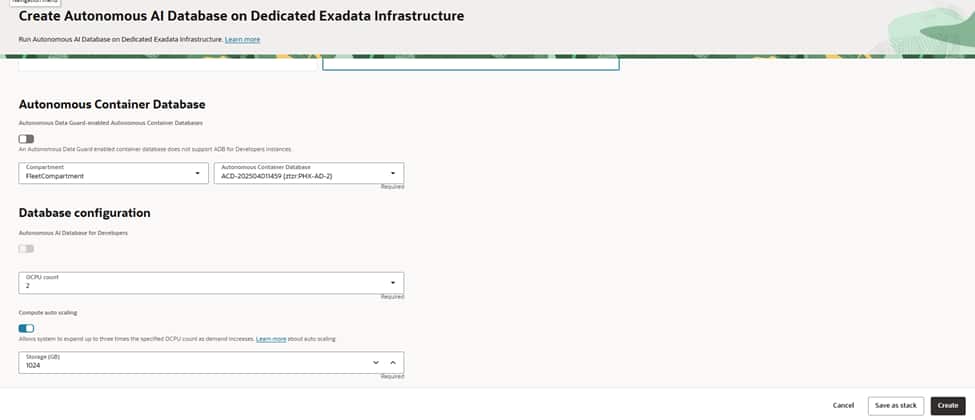
Choose an initial OCPU count that comfortably meets baseline demand. and set storage to cover current data plus growth headroom.
Enable auto scaling if you expect bursts; this lets the service elastically increase OCPUs during peak periods without manual intervention, helping you balance performance and cost.
Confirm the license model appropriate for your tenancy before proceeding.
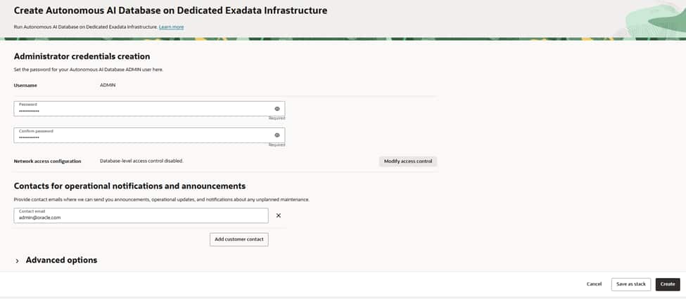
Create a strong ADMIN password following your organization’s policy and plan for regular rotation.
Define the database’s access posture—on Dedicated, private endpoints are recommended so traffic stays inside your VCN. If you use allowlists, configure them to limit client connections to specific subnets or CIDRs, and ensure route tables and NSGs permit only the minimum required access.
Add one or more operational email addresses (ideally a team distribution list) to receive announcements about maintenance, updates, and health notifications. Keeping a shared contact ensures the right people are informed during lifecycle events and helps streamline incident response and change management.
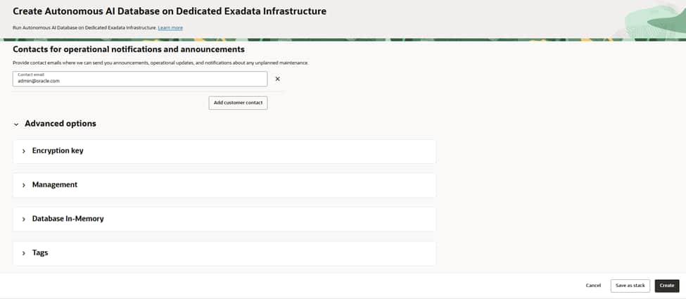
Review all your selections; name, compartment, ACD, OCPUs, storage, access controls, and advanced options, then create the database.
Provisioning typically completes in a few minutes on Dedicated Exadata. Once the lifecycle state is “Available”, the service is ready to accept connections and can be integrated into your application environment.
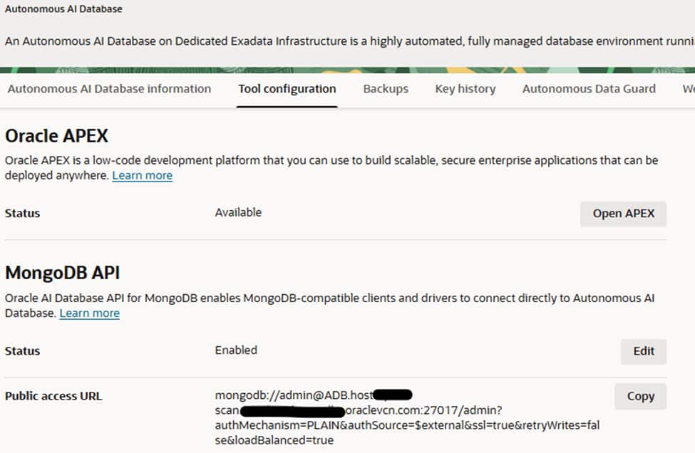
After creation of database click database name and go to Tool Configuration tab to be sure about whether MongoDB API is enabled or not.If not, click edit button and enable it to access database using MongoDB API interface
3)SETTING UP AUTONOMOUS DATAGUARD and AUTOMATIC FAILOVER
Enable Autonomous Data Guard – local standby (PHX)
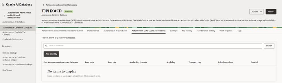
Begin on the primary Autonomous Container Database in PHX and open its Autonomous Data Guard associations. From here, initiate the process to add a standby.
This view shows you that there are currently no peer container databases linked. You will create one by adding a local standby that will live on dedicated Exadata capacity in the same region for low-latency, synchronous protection.
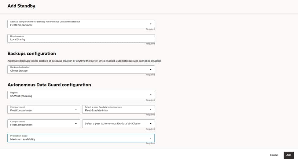
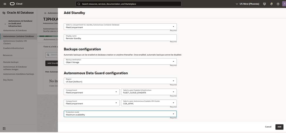
Start the Add Standby flow by confirming the compartment where this standby ACD will reside and give it a meaningful name such as “PHX-Local-Standby”.
Enable automatic backups and choose Object Storage as the destination to protect the standby’s control information and enable point-in-time recovery if needed. Remember that once automatic backups are enabled for the container, they cannot be disabled. Ensure the retention policy aligns with your data protection requirement
Configure the Autonomous Data Guard parameters by choosing the “US West (Phoenix)” region and selecting “Local Standby.”
Next, pick the Dedicated Exadata Infrastructure resource that will host the standby and then select the peer Autonomous VM Cluster in that infrastructure.
This VM cluster should be sized and aligned with your primary’s patch track and networking to ensure smooth role transitions and predictable performance.
Select the protection mode to “Maximum availability” to enable synchronous transport with automatic, zero data loss failover when conditions allow. This mode is ideal for same‑region local standbys because of the low network latency between the primary and standby clusters.
With these choices in place, proceed to add the standby.
OCI orchestrates creation, initial synchronization, and continuous redo apply.
After creation, return to the Autonomous Data Guard associations to verify status and health. You should see the peer ACD listed with role “Standby,” applying and transport lags near zero under normal operation.
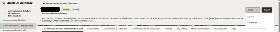
Using the actions menu at the top of the screen (on the right hand side). perform a switchover and monitor database statuses via the autonomous data guard groups tab.
Enable Autonomous Data Guard – remote standby (ASH)
Repeat the same steps for when we created the local standby on PHX region, but change the region name to Ashburn.
Pick the Dedicated Exadata Infrastructure resource that will host the remote standby, and then select the peer Autonomous VM Cluster in that infrastructure.
This VM cluster should be sized and aligned with your primary’s patch track and networking to ensure smooth role transitions and predictable performance.
4)CREATING KUBE CLUSTERS ON BOTH REGIONS(PHX,ASH)
Here are the steps to create and prepare OKE(Oracle Kubernetes Engine) clusters in both OCI regions: us-phoenix-1 (PHX) and us-ashburn-1 (ASH).
Create OKE clusters (repeat in PHX and ASH)
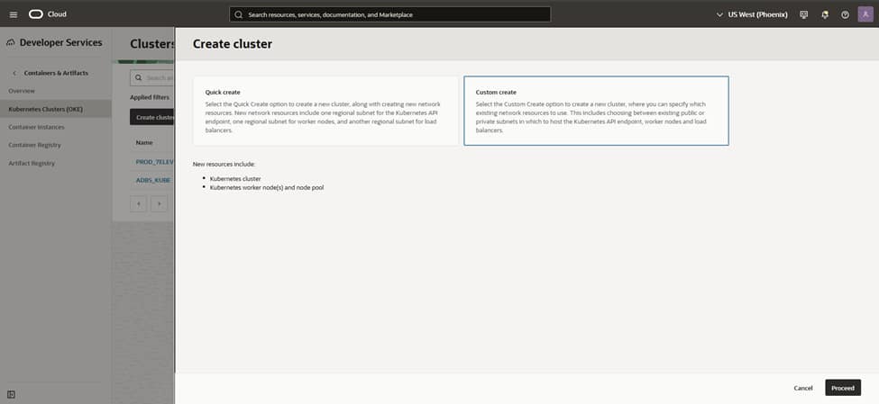
– Console: Developer Services > Kubernetes Clusters (OKE) > Create cluster > Custom create.
– Control plane:
– Endpoint type: Private (recommended) or Public depending on your access model.
– Networking: Select the VCN and cluster CIDRs (Service CIDR, Pod CIDR); use defaults unless you need custom ranges.
– Add-ons: Enable OKE-managed add-ons as offered (e.g., VCN-Native CNI, CoreDNS, Metrics Server, Kubernetes Dashboard as needed).
– Create the cluster (without nodes yet if you want fine control).
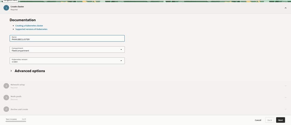
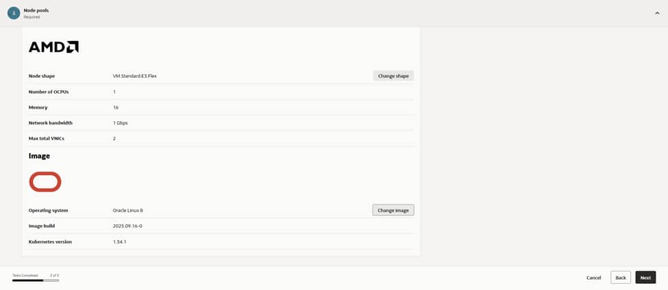
The process begins in the PHX region by assigning a clear name like PHXOKECLUSTER.
Selecting a supported Kubernetes version, and opting for VCN-native pod networking, ensures optimal performance and security. The review screen provides a summary of node and network settings. Once ‘Create’ is clicked, OCI initiates the cluster provisioning automatically.
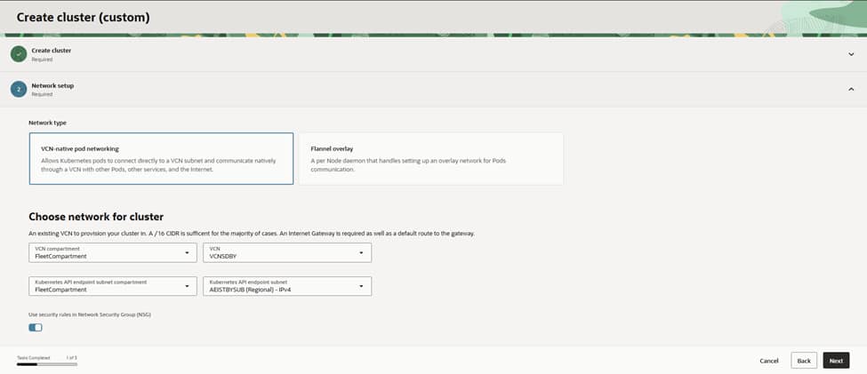
For networking, the choice of VCN‑native pod networking ensures that pods receive first‑class IPs within the VCN. This allows them to route cleanly to services, databases, and the edge.
The cluster is hosted in the VCN (named VCNDBDV), which is already configured with NAT and Service Gateways for private egress and OCI service access.
The Kubernetes API endpoint is placed into the APIEndpoint (Regional) IPv4 subnet to keep control traffic segmented. Given the requirements of an enterprise setup, the API endpoint remains private, relying on Bastion or VPN solutions for all administrative access
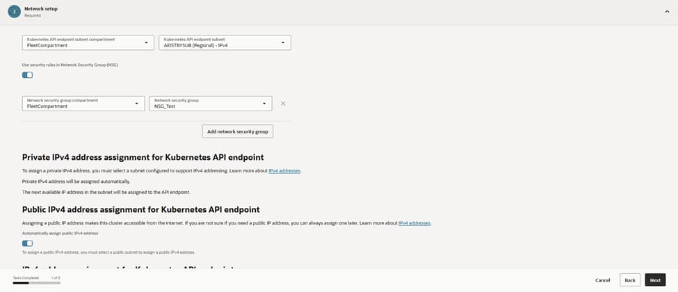
Security starts at the perimeter.
Attaching the NSG_Test network security group to the API endpoint ensures that ingress is strictly limited to port 443 from authorized admin ranges and CI/CD runners.
This configuration provides the necessary assurance that kubectl and controllers can reach the control plane without exposing it to the internet. Internally, route tables steer traffic via NAT while maintaining nodes without public Ips; a setup that aligns perfectly with a zero-trust posture.
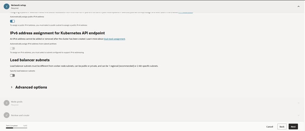
Load balancers receive dedicated lanes by designating specific subnets separate from the worker nodes. While public load balancers are reserved for internet‑facing applications, most services reside behind private load balancers, reachable only through the corporate network. This strategic separation simplifies firewall management and capacity planning for future requirements, especially during scale-out operations.
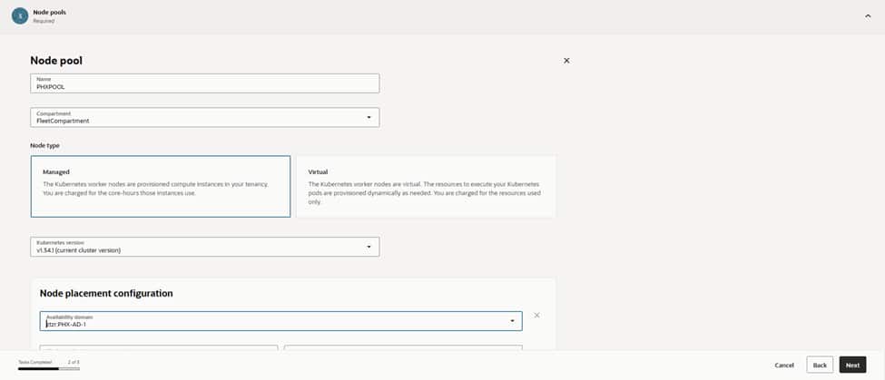
The process continues with the creation of the first node pool, designated as PRODPOOL to ensure its purpose remains clear in dashboards and alerts. Choosing “Managed” nodes allows for full OCI lifecycle handling, while matching the node pool’s Kubernetes version to the control plane prevents version skew. For maximum resilience, the configuration targets US‑PHX‑AD‑1 and spreads placement across multiple fault domains. This ensures that the infrastructure can withstand host‑level disturbances without affecting service SLOs.
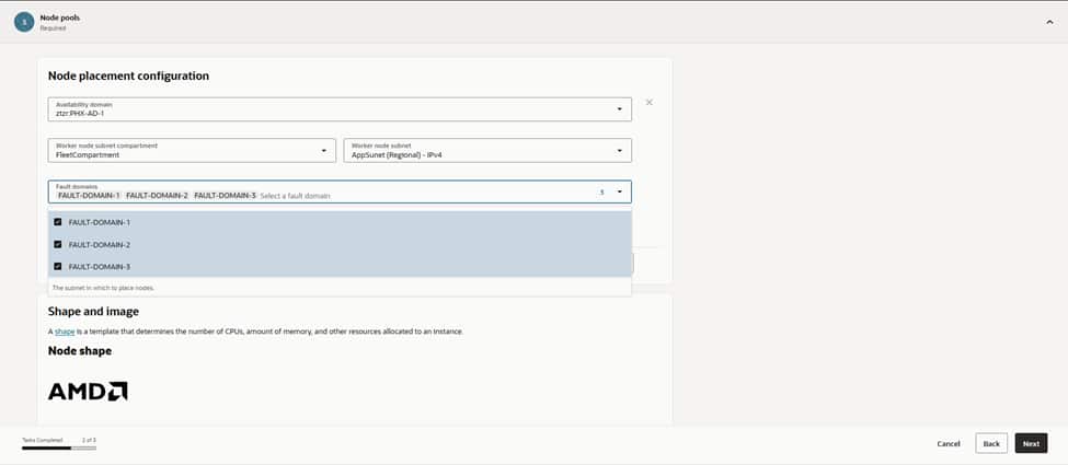
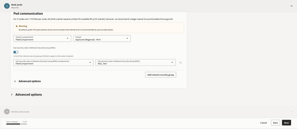
Worker nodes attach to the AppSubnet (Regional) IPv4 subnet, providing workloads with a dedicated address space distinct from the control plane and load balancers. The nodes, and their pod traffic, are bound to the MGL_Test NSG for east–west policy and app‑specific rules. This maintains a restrictive default stance that only permits genuinely necessary traffic. Crucially, nodes deploy without public IPs; egress traffic flows via NAT(Network Address Translation), while all inbound access reaches them exclusively through OCI load balancers.
With placement decided, the initial node count is set to a modest starting point, leaving sufficient room in subnets for future growth. Boot volumes remain at the default size. Application logs stream directly to centralized logging and any heavy local caching requirements can be addressed later. This configuration also provides the foundation to integrate the Cluster Autoscaler once real workload telemetry is available. This allows the fleet to expand and contract based on demand, while keeping costs in check.
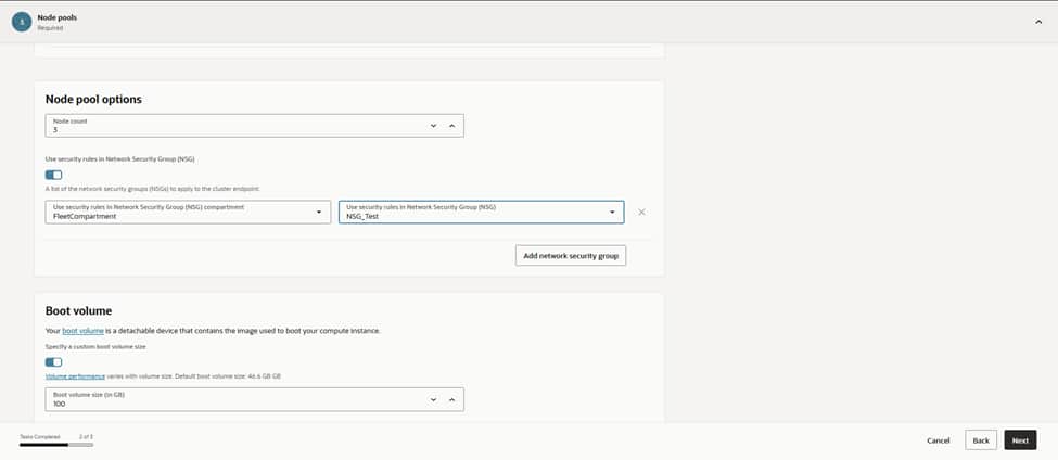
With placement decided, we set the initial node count to a modest starting point and left room in subnets for growth. Boot volumes stayed at the default size for now, since app logs stream to centralized logging, and any heavy local caching can be added later. This is also where we’ll wire in Cluster Autoscaler once we have real workload telemetry, letting the fleet grow and shrink around demand while keeping costs in check.
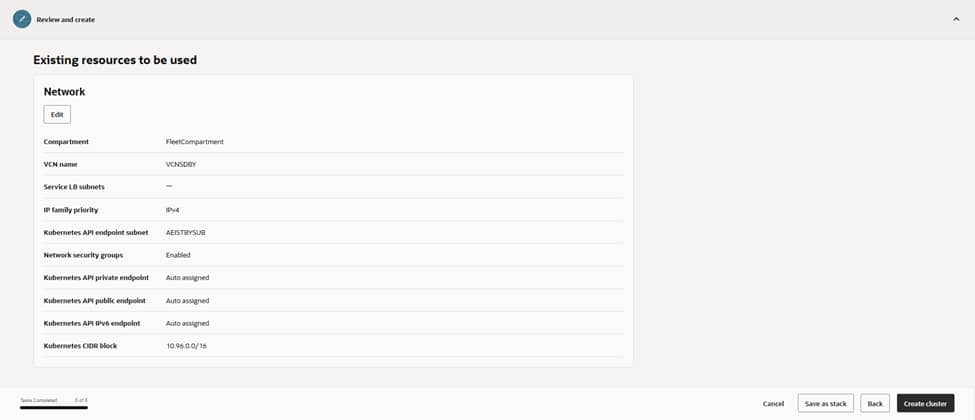
The final review screen summarizes the entire configuration. VCNDBDV serves as the network backbone. APIEndpoint (Regional) manages the control plane. AppSubnet (Regional) hosts the worker nodes. Security is maintained through NSG_Test and MGL_Test securing all ingress paths. The PRODPOOL node pool runs the selected Kubernetes revision on VM.Standard.E4.Flex shapes. Selecting ‘Create Cluster’ triggers OKE to orchestrate the control plane and nodes into an Active state, automatically provisioning all necessary cloud resources behind the scenes.
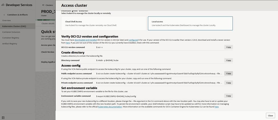
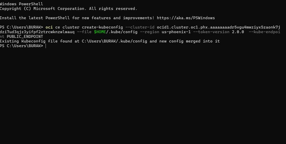
Configure kubectl access
– Cloud Shell or OCI CLI(Command Line Interface): Use “Access Cluster” in the OKE console to download/update kubeconfig.
– For private endpoint clusters, ensure you connect from within the VCN (e.g., OCI Bastion + SSH tunnel, VPN, or FastConnect).
– Verify: kubectl get nodes; kubectl get pods -A.
Install kubectl tool on bastion or on your client and configure to manage kube clusters
https://kubernetes.io/docs/tasks/tools/install-kubectl-windows
https://kubernetes.io/docs/tasks/tools/install-kubectl-macos
5)CREATING CONTAINER IMAGE USING MERN APP AND HAPROXY
The transformation of the MERN ecosystem (comprising MongoDB, Express, React, and Node.js) into a containerized architecture ensures maximum portability and environmental consistency. This process involves packaging each component into isolated Docker images, where specific Dockerfiles define the necessary runtimes and dependencies. By externalizing environment variables and optimizing image layers, the application maintains a lightweight footprint. This facilitates rapid deployment across different stages of the development lifecycle without configuration conflicts.
MERN application has to be containerized in an OCI image to be used in a Kubernetes cluster.
The following files need to be included in the MERN application:
- docker-compose.yml
- Dockerfile
- docker-entrypoint.sh
A docker-compose.yml is essential to be able to build the image:
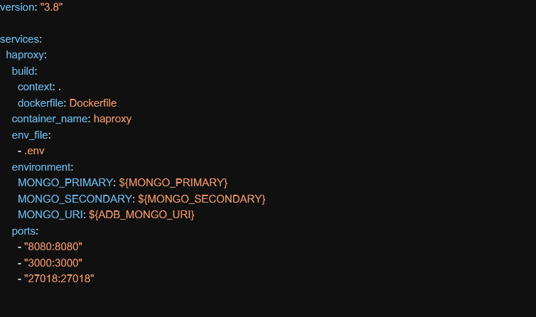
In this file above, a container name needs to be provided and ports 8080, 3000 and 27018 need to be exposed outside image:
- 8080 – port for application connections
- 3000 – communication port between server and client
- 27018 – port exposed by haproxy for database connections
All these ports can be adjusted and other values can be used.
Dockerfile – when image gets instantiated:

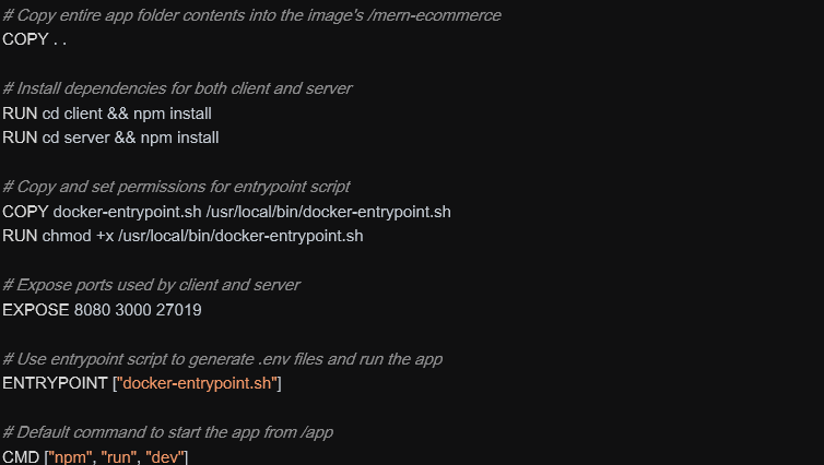
When image starts, it install npm libraries and run the docker-entrypoint.sh script.
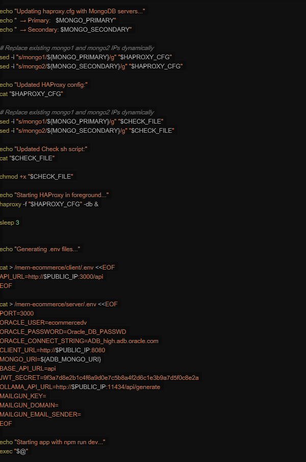
docker-entrypoint.sh script is launched to configure environment variables and to start the application when container gets instantiated:
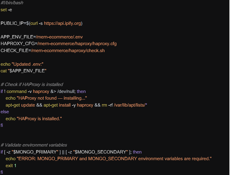
HAProxy Configuration
HAProxy distributes incoming traffic across multiple backend database servers to:
- Prevent overload on a single server
- Improve application performance
- Increase system scalability
It helps keep applications online even if a server fails:
- Automatically detects unhealthy servers
- Stops sending traffic to failed servers
- Supports failover setups
This is critical for production systems and large-scale websites.
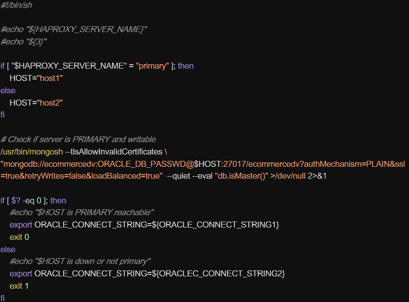
That’s why, an haproxy process runs inside each mern container image and was configured as:
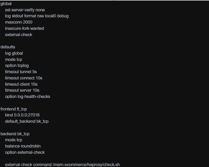
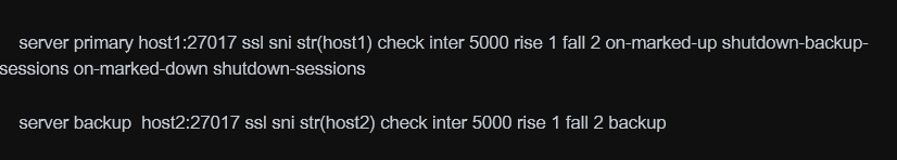
The haproxy balance requests for high-availability between the two autonomous databases instances which are based on host1 and host 2. The values for host1 and host2 are added by the script above when the container image is launched.
The check.sh server is the one used as external check by haproxy to test if database is running:
6)CREATING CONTAINER REGISTRY AND PUSHING IMAGE TO OCI
To create the container image, run this commands:
docker-compose build –no-cache
Docker image will be created.
Then tag your image to the corresponding OCI region where it will be uploaded:
docker tag <image_name>:latest <region_id>.ocir.io/<oci_registry_name>/<tag_name>:haproxy
Push the image to the specified registry in that region:
docker login <region_id>.ocir.io
docker push <region_id>.ocir.io/<oci_registry_name>/<tag_name>:haproxy
7)DEPYLOYING CONTAINER IMAGE TO ORACLE KUBERNETES CLUSTER
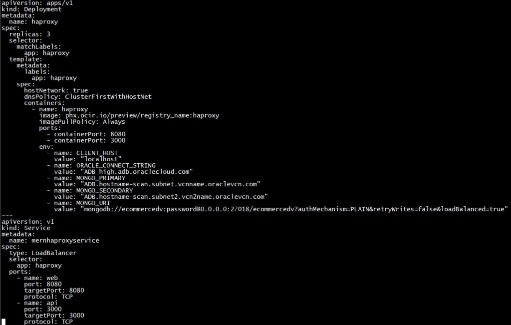
Before deploying our image we need to create a yaml file to define attibutes of image as likely below;
To deploy our image to our Kube Cluster we need to install kubectl client in our local client.Please check proper client for your environment.
As the next step we will configure our client to access our kubernetes cluster.Cluster information can be gathered from oci kubernetes cluster details.

Using the yaml file that we created , using the command below we can deploy our container image which will take a couple of minutes for the first deployment.
kubectl create -f .\mern_ecommerce.yaml
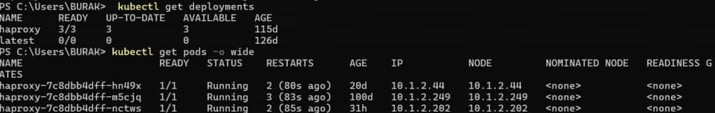
Also if you want to check status of your pods and deployments in your kubenetes cluster those commands are usefull
kubectl get deployments
kubectl get pods -o wide
8)CREATING AND CONFIGURING LOAD BALANCER TO ACCESS KUBE CONTAINERS
Here are the steps needed to expose Kubernetes workloads on OKE through an OCI Load Balancer. You can use either: (A) a Service of type LoadBalancer per app, or (B) an Ingress controller (recommended) with one Load Balancer fronting many apps.
1) Prerequisites
– OKE cluster running and kubectl access.
– VCN with subnets for Load Balancers (public for internet access, private for internal).
– IAM policies allowing OKE to create/load-balance resources.
– NSGs/security lists allowing required ports from the LB to worker nodes.
2) Decide your exposure model
– Direct Service type LoadBalancer: simplest for TCP/HTTP services, one LB per Service.
– Ingress controller (e.g., NGINX/Traefik): one LB, multiple apps via host/path routing and TLS.
– For high-throughput TCP/UDP, consider OCI Network Load Balancer (NLB) via Service annotations.
3) Create or select LB subnets
– Public access: use a public subnet for the LB; ensure Internet Gateway and route table exist.
– Private access: use a private subnet; clients connect via VPN/FastConnect/Bastion.
– Attach an NSG for fine-grained rules (e.g., allow 80/443 inbound).
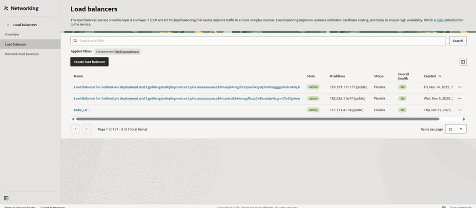
Go to the OCI Networking > Load Balancers page to verify the network landscape before launching a new build for the Kubernetes front door. The objective is to expose workloads running on the PHX cluster behind a governed OCI Load Balancer while maintaining the privacy of the worker nodes. Clicking ‘Create load balancer’ initiates the configuration, routing traffic from the edge directly to the Kubernetes services.
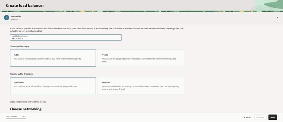
The process begins by assigning a clear name (PHXKUBELB) and setting the visibility to Public to facilitate internet-facing traffic. Selecting an Ephemeral public IP allows OCI to assign the address automatically at creation. For consistency, in both operations and cost, these naming and visibility choices are intentional. Public settings serve edge services, while private settings remain reserved for internal-only applications
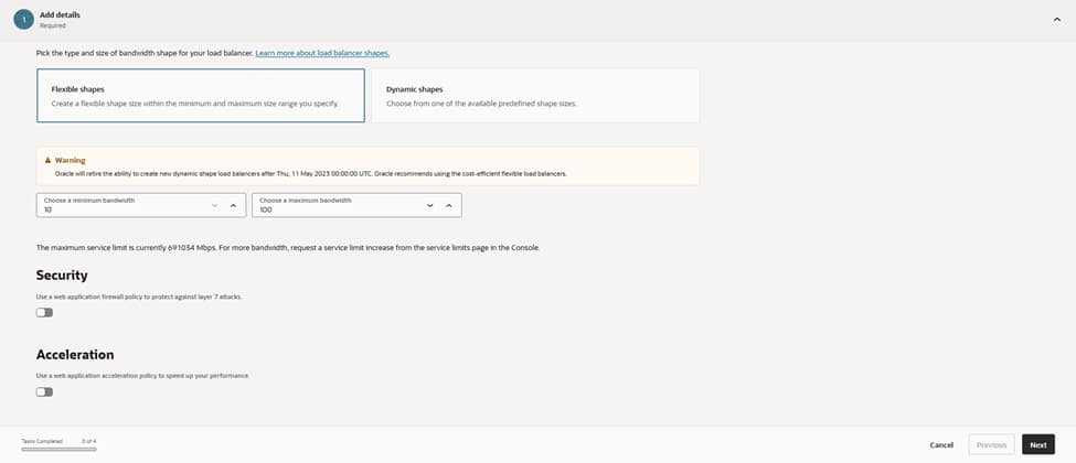
On the shape screen, selecting the Flexible option allows for precise control, setting both the initial minimum and maximum bandwidth to 10 Mbps. Flexible shapes in OCI provide the ability to dial capacity up later without a rebuild. This is ideal when establishing a traffic baseline. Optional security acceleration remains disabled for now, with the understanding that this feature can be activated once real throughput requirements are clearly defined.
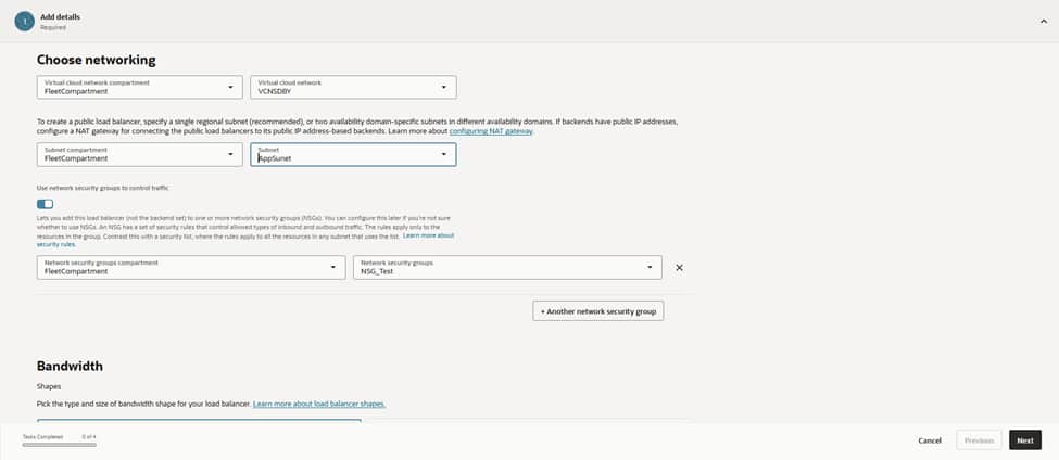
The configuration then moves to networking. The load balancer anchors to the VCN named VCNDBDV and resides within the AppSubnet (Regional) IPv4 subnet. This subnet is specifically designed for north–south traffic, providing a clean route to the cluster’s node subnets.
Attaching the NSG_Test network security group ensures that only approved sources and ports reach the VIP. Utilizing NSGs rather than broad security lists keeps guardrails tight, specific, and easily auditable.
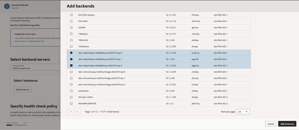
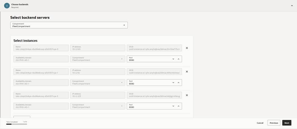
With the front door established, the next step involves registering the backends that represent the Kubernetes entry point. Adding the worker node instances as backends, and setting the port to 8080, ensures the load balancer communicates directly with the NodePort/Ingress service listening for traffic.
Integrating multiple nodes creates inherent resiliency. If one node drains or fails, the load balancer automatically continues routing to the remaining healthy nodes. This configuration aligns with the overall strategy of keeping nodes private, while exclusively exposing the load balancer to external traffic.
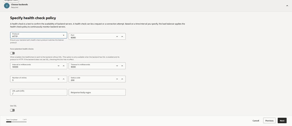
Maintaining system health is a priority. The configuration defines an HTTP health check on port 8080 with a 10‑second interval, a 3‑second timeout, and a requirement of three successes, before marking a backend as healthy.
Limiting retries ensures that failover remains snappy under fault conditions. This policy continuously probes each node’s service endpoint. This ensures that traffic only lands on backends that are actually ready to serve. In doing so, we protect the user experience from potential node-level failures.
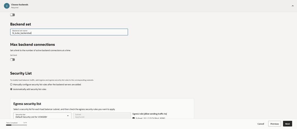
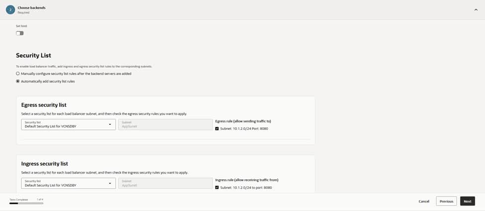
This configuration groups the designated backends into a backend set named lb_kube_backendset. We keep the maximum backend connections at their default values. Enabling “automatic security list updates” ensures that the correct ingress and egress rules for port 8080 are applied to the load balancer subnet.
Auto-managing these rules eliminates potential misconfigurations and maintains a predictable data path as nodes are added or rotated in the future. This automation reinforces the security architecture by ensuring the network policies always stay synchronized with the active backend infrastructure.

Because the Kubernetes workloads are stateless, session persistence remains disabled. If an application requires sticky sessions, this is the point where cookie-based persistence is enabled. However, in this architecture, consistent hashing at the application layer and idempotent requests make stickiness unnecessary. This improves the overall load distribution across the cluster.
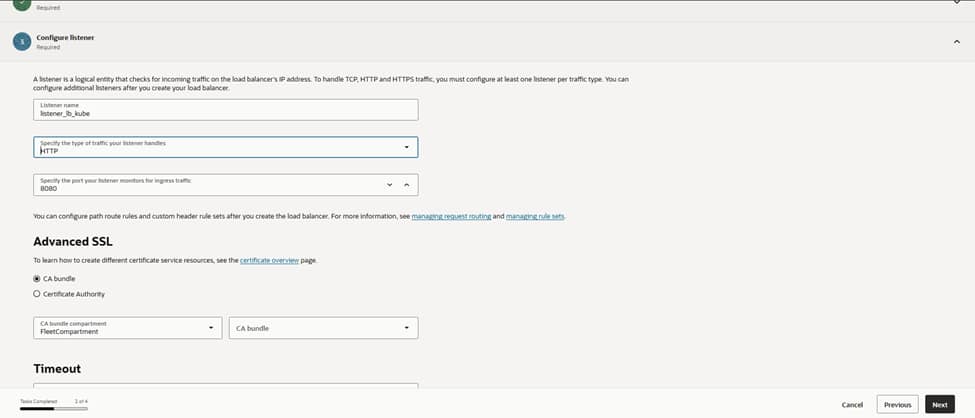
For the listener, the configuration establishes lb_listener using the HTTP protocol on port 8080, binding it directly to the lb_kube_backendset. This serves as the single entry point that accepts client connections and hands them off to the healthy backends.
Should the need for TLS arise, attaching a certificate from OCI Certificates and switching the listener to HTTPS remains a straightforward option that requires no architectural changes.
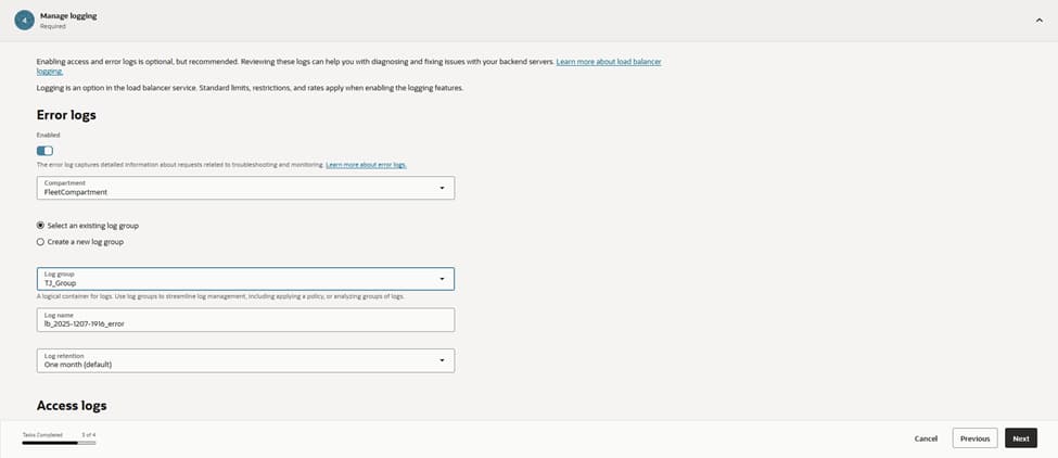
The configuration enables error logging and targets the existing log group, LB_group, to write to a dedicated log . Centralized logging is crucial for diagnosing intermittent 5xx responses and for monitoring health probe failures.
This setup also feeds into the monitoring pipelines, allowing for automated alerts on anomaly spikes and backend flaps. Maintaining these logs ensures full visibility into the traffic flow and provides the data necessary for rapid troubleshooting and performance auditing.
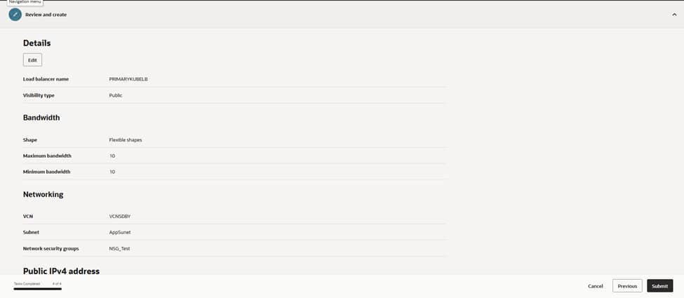
On the final review page, the configuration undergoes a verification of the essential settings: PRIMARYKUBELB as the name, Public visibility, a flexible shape with 10/10 Mbps bandwidth, and the network parameters set to VCNDBDV and AppSubnet, with NSG_Test applied.
Upon submission, OCI provisions the load balancer and assigns a public IP address. A simple curl against http://<public-ip>:8080 confirms reachability. The health dashboard reflects a green status for all Kubernetes node backends. This successful validation marks the completion of the external entry point configuration.
9)CREATING AND TUNING LOAD TESTING SCENARIOS FOR JMETER
JMeter is an open-source tool used for load testing, performance testing, and functional API testing.
The creation of a performance baseline begins by designing realistic traffic patterns within Apache JMeter to simulate actual user behavior. This process involves defining Thread Groups that represent concurrent users accessing the MERN application through the OCI Load Balancer. By configuring the number of threads, ramp-up periods, and loop counts, the scenario mimics various stress levels, from steady-state production traffic to sudden spikes. This systematic approach ensures that the performance metrics reflect how the architecture handles real-world concurrency and resource contention.
If you’re working with APIs (REST/SOAP), JMeter can simulate multiple users sending requests and measure how your API behaves under load.
Install & Launch JMeter
Step 1: Install
- Install Java (JDK 8+)
- Download JMeter from the official site
- Extract the zip file
Step 2: Run
- Mac/Linux: bin/jmeter
The GUI will open.
Then create a JMeter test plan using the API commands exposed by MERN application on port 3000.
One can define user defined variables, like how many threads to spawn inside test:
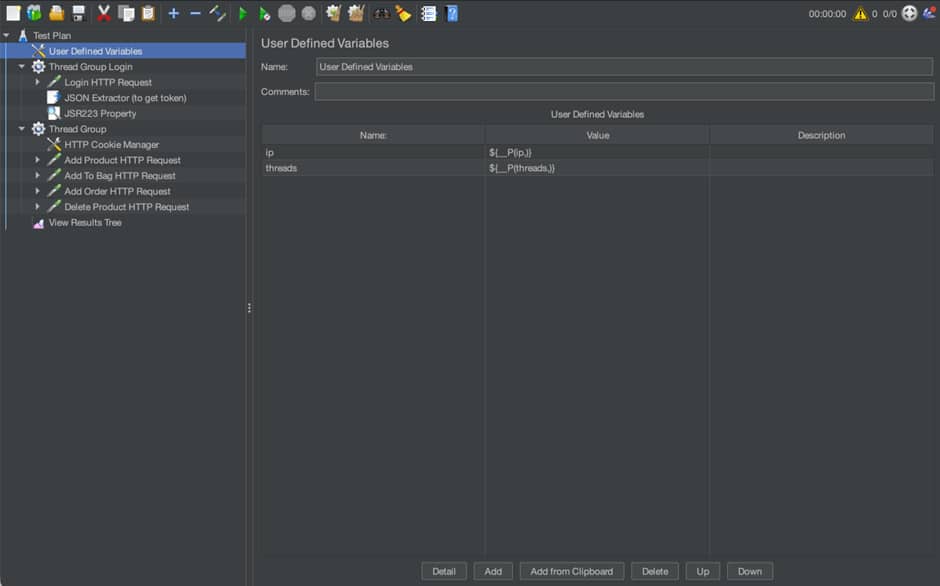
Then, there are two main threads:
- Connect to the application using the token returned – Group Login
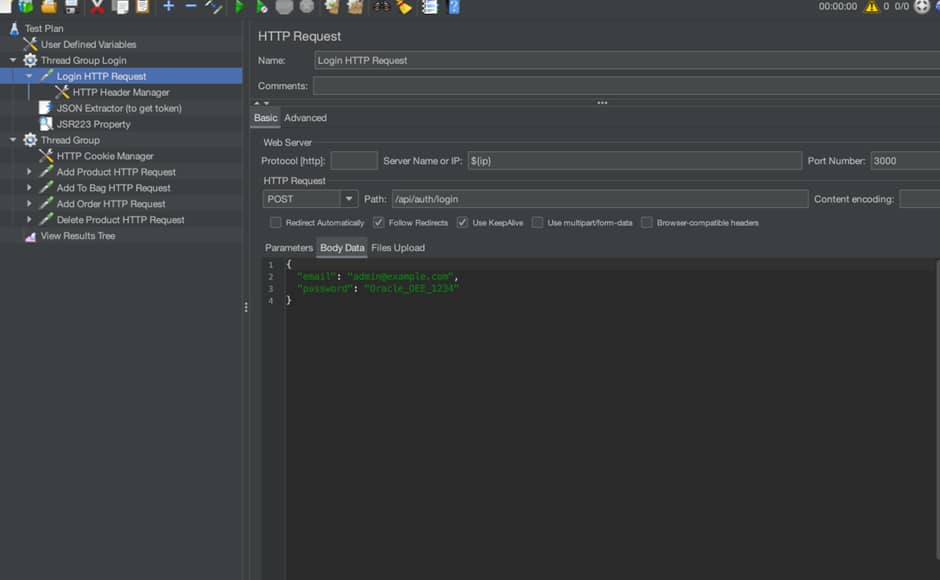
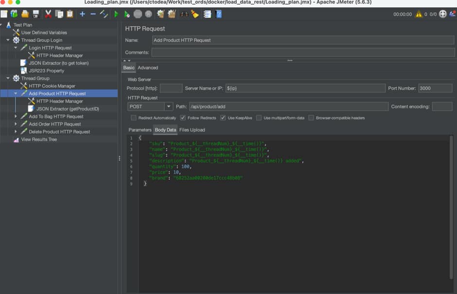
2. Run API commands against the MERN application
In conclusion, this guide establishes a robust and secure framework for deploying a cross-region high-availability architecture on Oracle Cloud Infrastructure (OCI).
By integrating self-managed Bastion hosts for secure administrative access, and deploying Autonomous Data Guard for cross-region redundancy and disaster recovery, the architecture delivers exceptional resilience and ensures strong data integrity.
Containerized applications deployed on Oracle Kubernetes Engine (OKE), combined with HAProxy for database load balancing, and OCI Load Balancers for secure traffic management, create a highly scalable and high-performance production environment.
Validated through comprehensive load testing with JMeter, this step-by-step methodology offers a definitive roadmap for building modern, disaster-resistant Mongo API for Oracle on OCI.
Resources