This blog post covers steps to configure a standby Oracle database across regions using remote virtual cloud network (VCN) peering. VCN peering connects two VCNs. If the VCNs are present in the same region Local VCN Peering can be set up using local peering gateways (LPGs). Remote VCN peering is the process to connect two VCNs in different regions but the same tenancy, such as US East (Ashburn) and US West (Phoenix).
Peering allows resources in one VCN to communicate with resources present in the other VCN using private IP addresses without routing the traffic over the internet. To peer with a VCN in another region, your tenancy needs to be subscribed to that region. The two VCNs that you plan to peer also need non-overlapping CIDRs.
In part one of this blog, we cover the steps to set up VCN peering:
- Create a VCN and attach a dynamic routing gateway (DRG).
- Create remote peering connections (RPCs) and establish a connection.
- Configure route tables and security lists.
After VCN peering is set up, in part two, we provision an Oracle database using Database Systems and associate it with a standby database running across in another region.
Now let’s go into the details of each step. The following diagram shows the network and other resources that we’re using. Region 1 is US East (Ashburn), and Region 2 is US West (Phoenix).
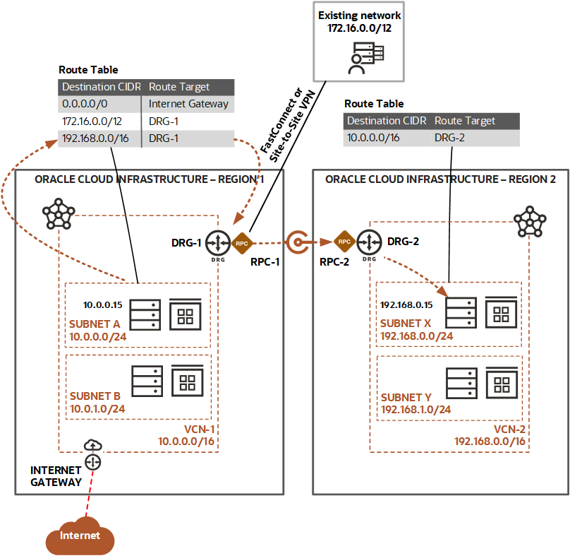
Create the VCN and attach a DRG
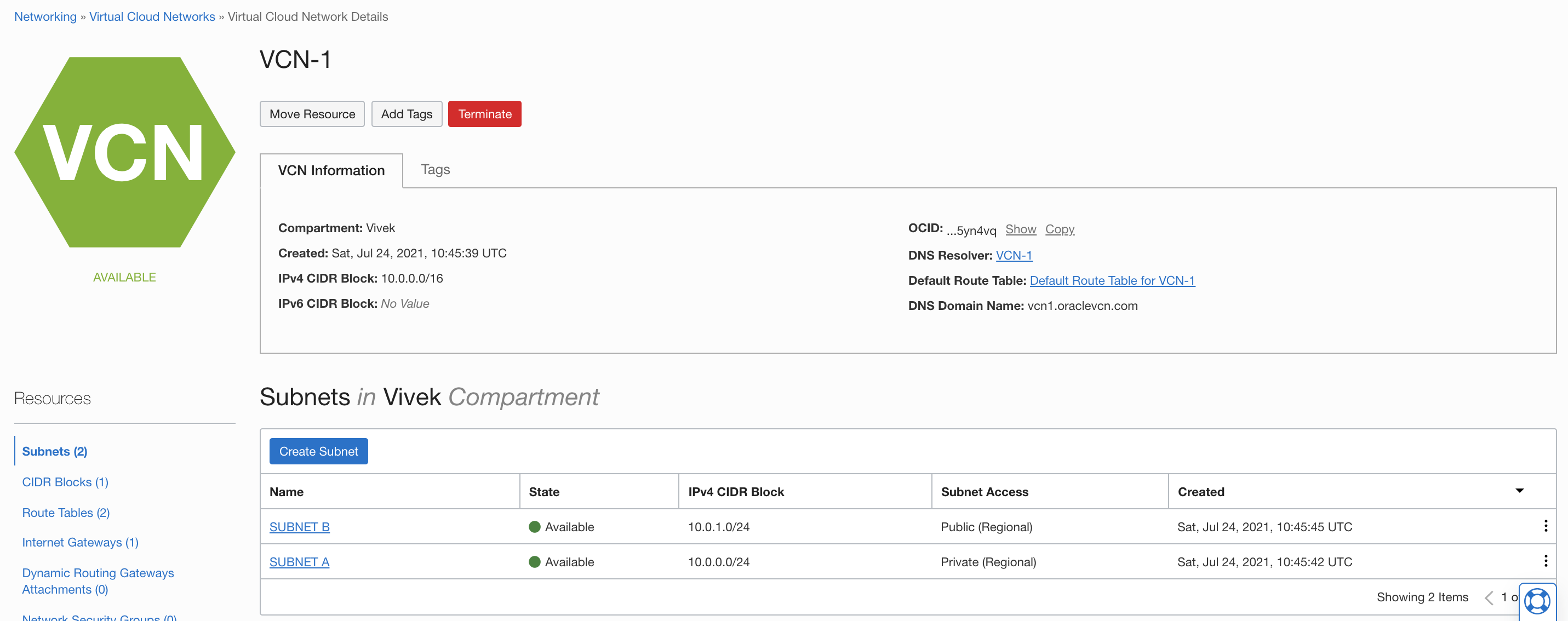
Log in to Oracle Cloud Infrastructure (OCI). Verify that the region selected is US East (Ashburn). Navigate to Networking and click Virtual Cloud Networks. Create a VCN using the VCN Wizard.
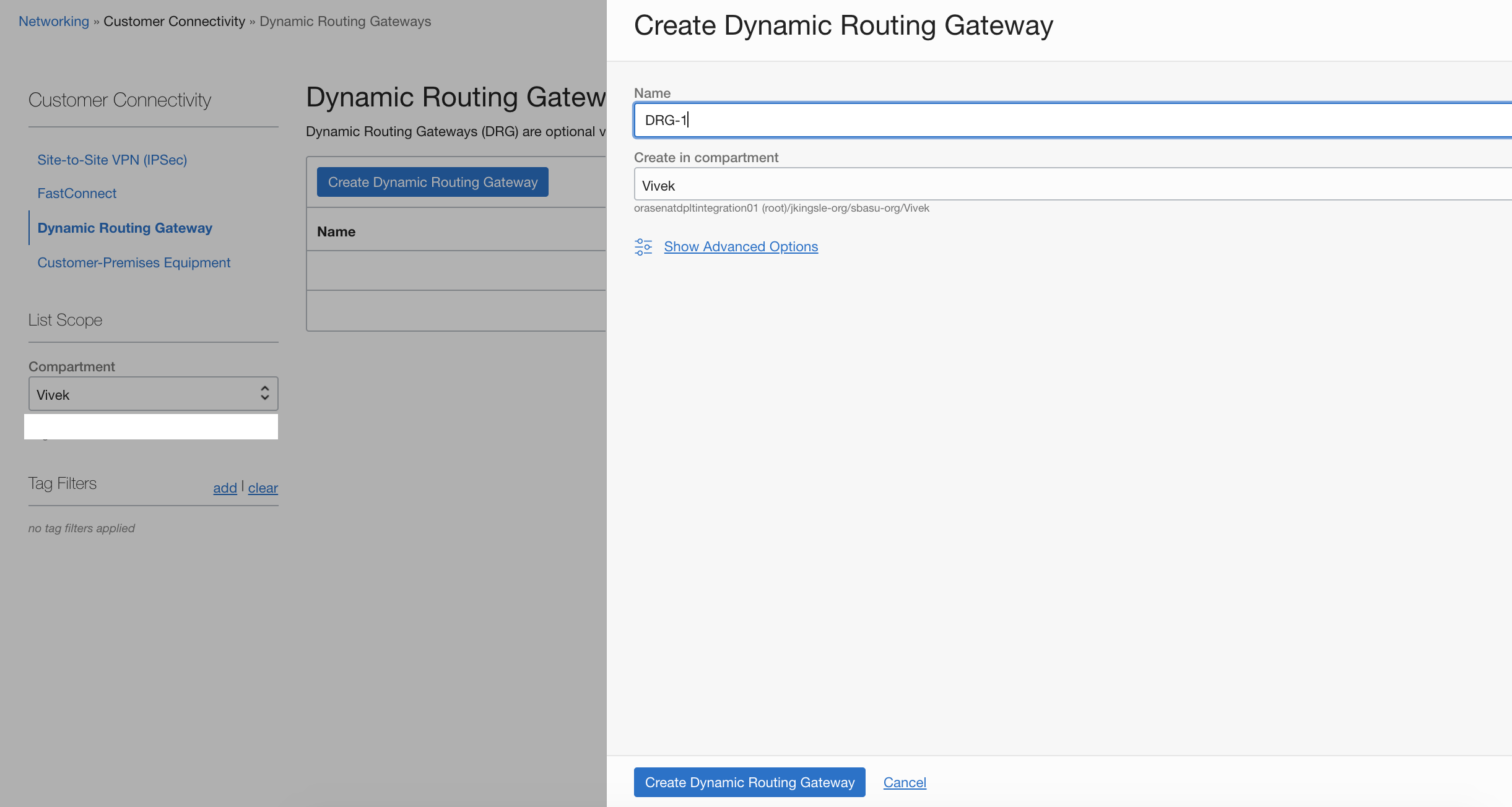
Under Networking, navigate to Customer Connectivity and click Dynamic Routing Gateways. Click Create Dynamic Routing Gateway. In our example, we use the name DRG-1. Select the compartment and click Create Dynamic Routing Gateway.
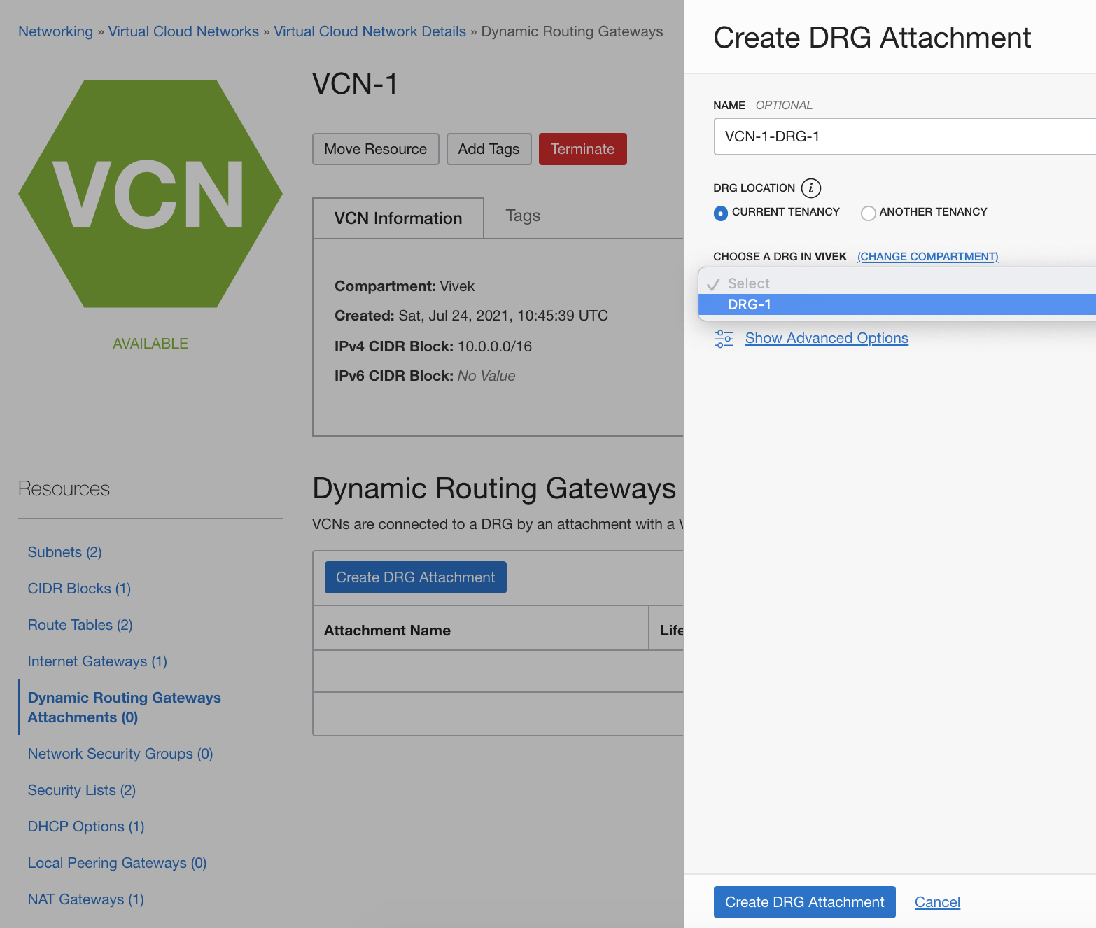
On the Virtual Cloud Network Details page for your VCN, click Dynamic Routing Gateways Attachments and then click Create DRG Attachment. Our example uses the name VCN-1-DRG-1. For the DRG, choose the DRG that you created and click Create DRG Attachment.
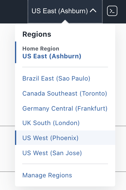
In the Console, click the current region name and select your second region, US West (Phoenix).
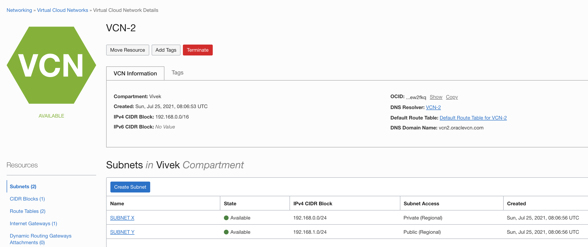
Follow the same steps you used for the primary region to create a VCN, DRG, and attach the DRG to VCN. This example uses the following details:
- VCN name: VCN-2
- CIDR block: 192.168.0.0/16
- Subnet X: 192.168.0.0/24
- Subnet Y: 192.168.1.0/24
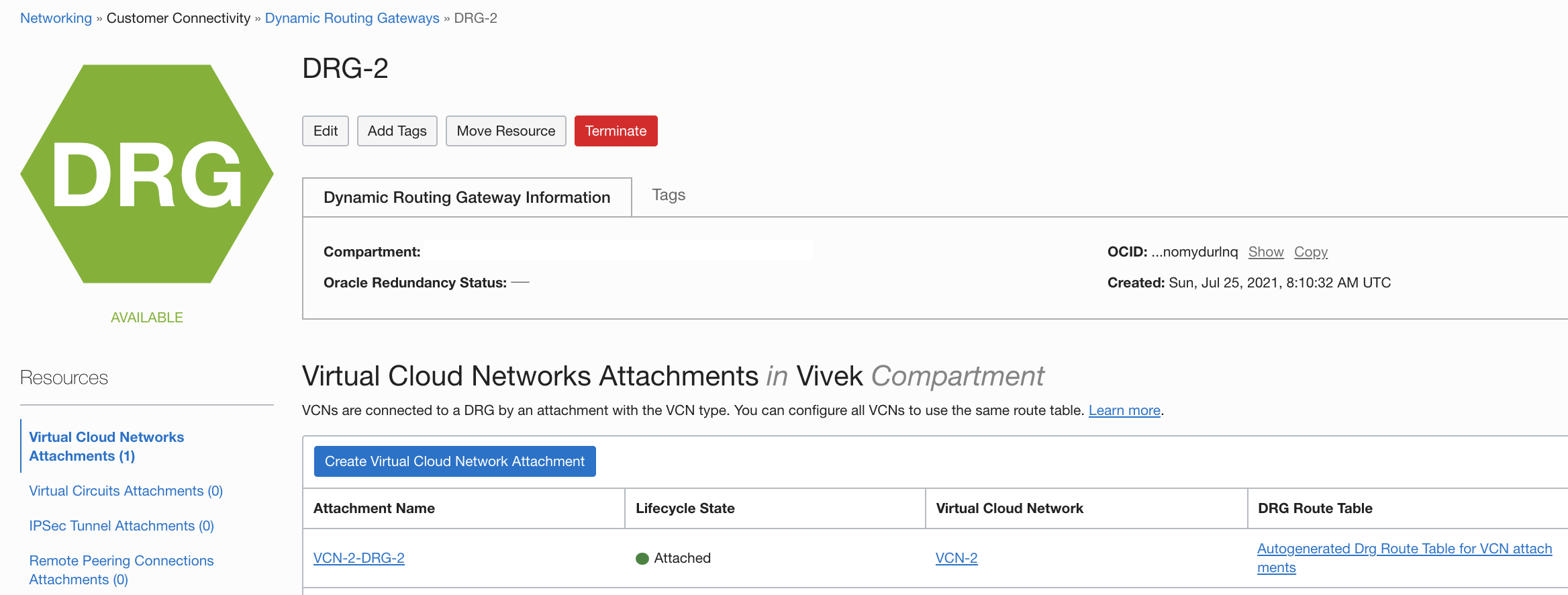
- DRG name: DRG-2
- DRG attachment name: VCN-2-DRG-2
Create RPCs and establish a connection
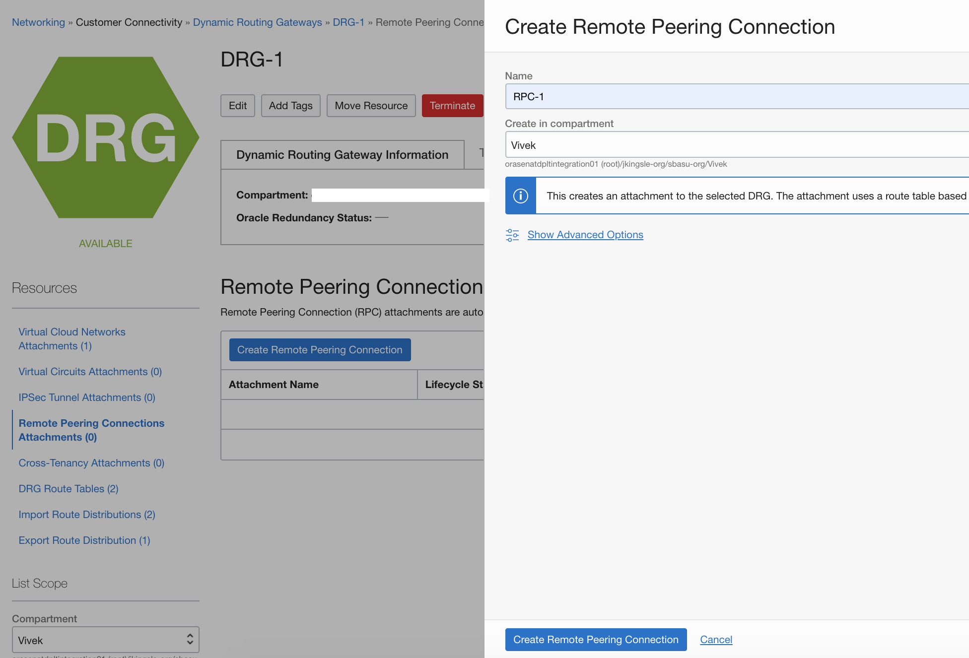
Navigate to Dynamic Routing Gateways and click on DRG-1
Navigate to the Dynamic Routing Gateways page and click DRG-1. Click Remote Peering Connections Attachments and the click Create Remote Peering Connection. In this example, we use the name RPC-1. Select the compartment and click Create Remote Peering Connection.
In the OCI Console, click the current region name and select the second region, US West (Phoenix). Create the remote peering connection, RPC-2.
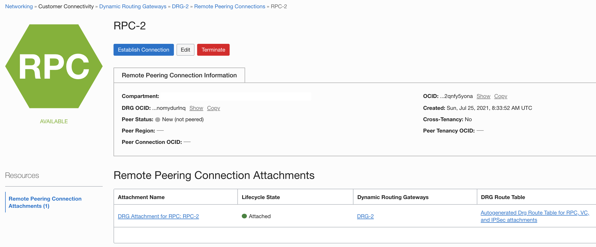
Navigate back to Networking. Under Customer Connectivity, select Dynamic Routing Gateways, then DRG-2, and under Remote Peering Connections, choose RPC-2. Copy the OCID.
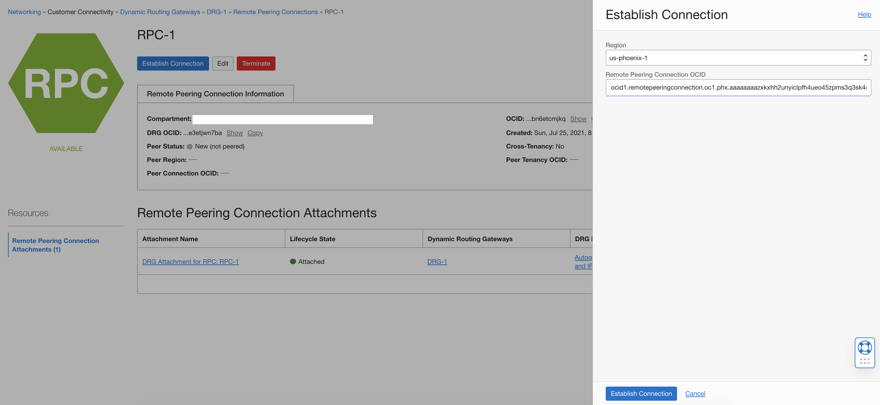
Change the region back to US East (Ashburn) and navigate to RPC-1. Click Establish Connection. Select US-phoenix-1 for the region and enter the OCID that you copied. Then click Establish Connection.
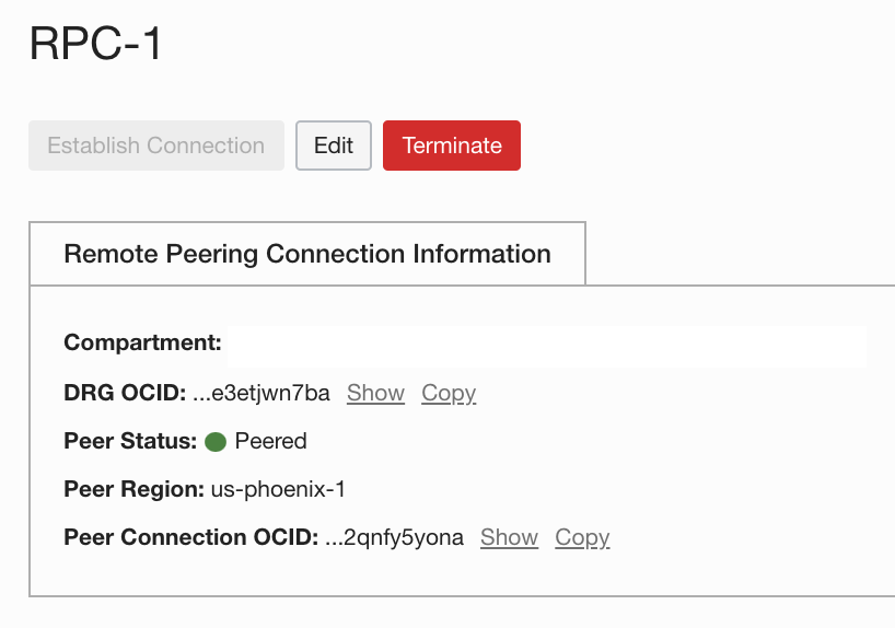
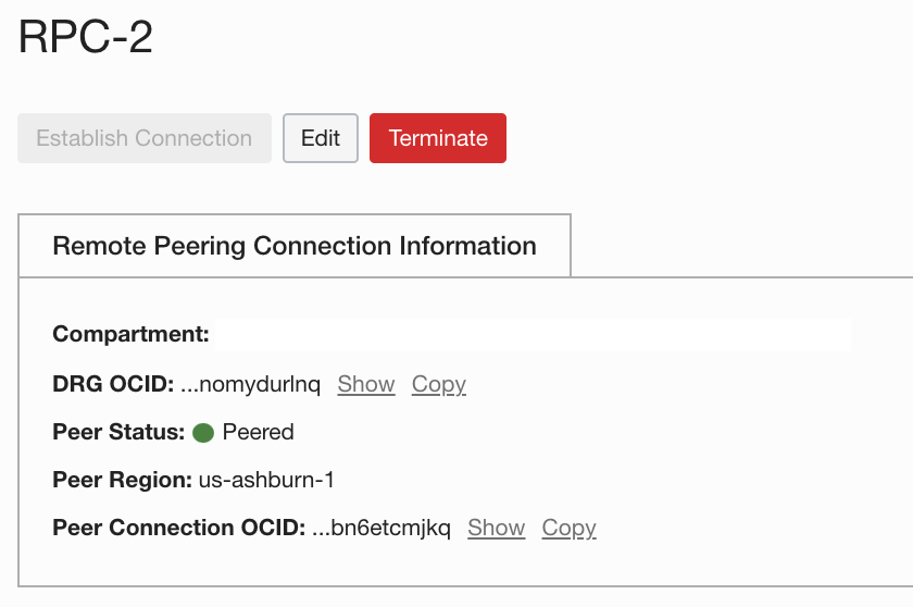
Confirm that the peer status for both RPC-1 and RPC-2 has changed to “Peered.”
Configure route tables and security lists
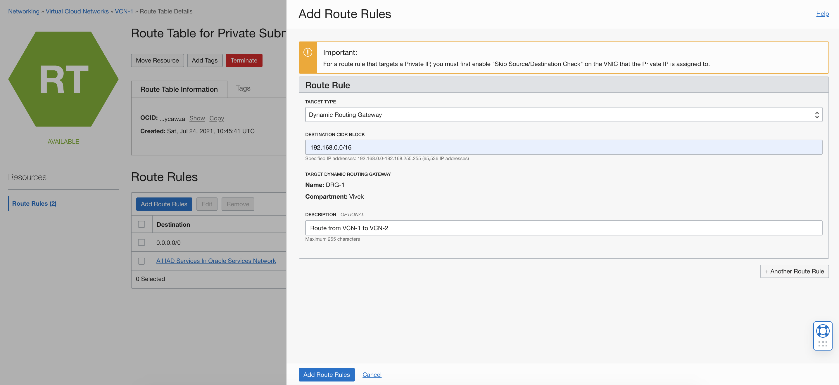
Navigate to the Route Table page for VCN-1 Subnet A and add a route rule. Use the target type Dynamic Routing Gateway and set the CIDR block to 192.168.0.0/16. Then click Add Route Rule.
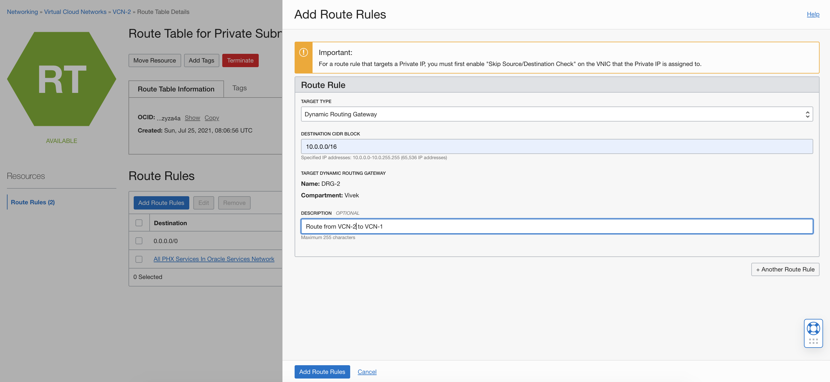
On the Route Table page for VCN-2 subnet X, add a route rule. Use the target type Dynamic Routing Gateway and set the CIDR block to 10.0.0.0/16. Then click Add Route Rule.
Add the following rules to the security lists:
- Ingress rules for the types of traffic that you want to allow from the other VCN
- Egress rule to allow outgoing traffic from your VCN to the other VCN
To be continued
In part two of this blog series, we discuss about provisioning an Oracle database in Oracle Cloud Database Systems and create a disaster recovery or standby database across regions using remote VCN peering.