Oracle and VMware have a fully certified and supported software-defined data center (SDDC) solution called Oracle Cloud VMware Solution, available in all global cloud regions. This solution is a dedicated, zero trust, cloud native, VMware-based environment that enables enterprises to easily move their production VMware workloads to Oracle Cloud Infrastructure (OCI).
In a previous blog, I discussed how to attach a public IP to a VM when creating a demilitarized zone (DMZ), for example. Currently in OCI, within a route table, we can either have a route to the internet through a NAT gateway or an internet gateway, not both. This binary causes a problem for customers who want to host both internal VMs and internet-facing VMs because they need both types of gateways.
We can get around this problem by configuring multitenancy within NSX-T, either by using separate NSX Edge infrastructure, as described in my post, A Detailed Guide to Deploy a DMZ on NSX-T for Oracle Cloud VMware Solution or following the release of NSX-T 3.0, using the method described in this post with the new virtual routing and forwarding (VRF) gateway. Implementing multitenancy in this way, without having to deploy several NSX Edge appliances, provides an easy method to scale out and spares valuable resources.
To simplify the understanding of VRFs, they’re the layer-3 equivalent of a VLAN. With VRFs, we can achieve a complete data plane isolation for each tenant. The biggest advantage of using VRFs is the ability to eliminate the need to create dedicated Tier-0 Gateway and separate NSX edge infrastructure to achieve multitenancy within NSX-T.
What to expect
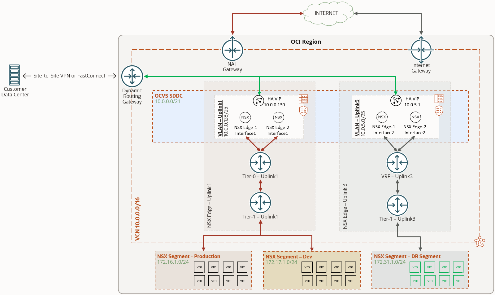
During the deployment of an SDDC, the automation configures a VLAN named Uplink1 in OCI, for all north-south traffic for the NSX overlay segments and provides customers with access to their VMware virtualization components, such as vSphere, NSX-T manager, HCX, and the ESXi hosts. OCVS SDDC is also confiugured with an Uplink 2 VLAN, which is ready to be configured for scaling out the NSX-T overlay, such as deploying a DMZ or VRF.
This blog has some optional steps to create an Uplink 3 VLAN, if Uplink 2 VLAN is already being used for other purpose. It is important to understand that during this process customers will experience a few seconds of downtime to their workloads on existing overlay segments. In the following diagram, we can see the high-level architecture we will be implementing. Uplink 1 VLAN is configured during the deployment of the SDDC, while the uplink 3 VLAN and its corresponding configuration are shown.
To deploy VRFs within VMware Solution, we perform the following steps:
-
Change the settings on existing Logical Switch and VCN Segment to allow VLAN trunking
-
Create a VLAN within OCI for uplink purposes
-
Create and attach virtual network interface cards (VNICs) on each ESXi host for the new VLAN.
-
Create transport zone and transport node profile.
-
Create a VLAN backed segment
-
Add a VRF on the existing tier-0 gateway and create a tier-1 gateway for the new uplink VLAN.
-
Create an overlay segment attached to the tier-1 gateway with the appropriate NAT rules.
Preparing to deploy NSX-T VRF gateway
It is recommended to gather the below information for easy access of all the environment details that is required for the deployment. We will update some of these fields after completing the initial few sections.
| VCN CIDR Block | 10.0.0.0/16 | |||
| VLAN Details |
||||
| NSX Edge Uplink1 VLAN | CIDR | 10.0.0.128/25 | ||
| VLAN Tag | 3863 | |||
| VLAN Gateway | 10.0.0.129/25 | |||
| NSX Edge Uplink2 VLAN (if using Uplink2 VLAN) |
CIDR | 10.0.1.0/25 | ||
| VLAN Tag | 2103 | |||
| VLAN Gateway | 10.0.1.1/25 | |||
| Three available IPs | 10.0.1.2 | 10.0.1.3 | 10.0.1.4 | |
| NSX Edge Uplink3 VLAN (if using Uplink3 VLAN) |
CIDR | |||
| VLAN Tag | ||||
| VLAN Gateway | ||||
| Three available IPs | ||||
Before we deploy a VRF gateway, let’s prepare the environment to allow several VLANs to exist within NSX. This action will disrupt traffic to existing VMs for a couple of minutes. It is recommended to perform this activity during a planned maintenance window.
Enable VLAN Trunking on the Logical Switch
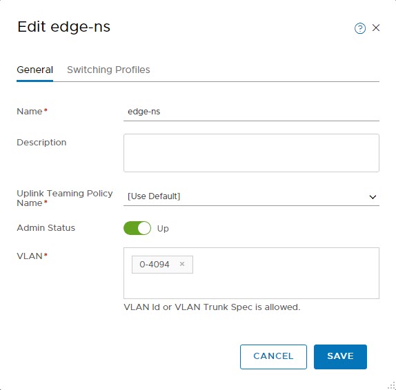
In order to allow several VLANs on the existing logical switch, let’s edit the edge-ns switch used by Uplink1.
- Refer to the VMware docs to access Logical Switches in NSX Manager
- In short, log into the NSX manager and select the Networking tab on the top
- Switch to Manager mode by using the toggle on the top-right and select Logical Switches on the left
- Select the existing edge-ns logical switch. Notice that it currently allows the VLAN ID of the Uplink1 VLAN
- Important: the following change will disrupt traffic to VMs on existing overlay NSX Segments
- Edit the logical switch and change the VLAN to allow all VLAN IDs, i.e., 0-4094
- Click Save and you can notice the traffic to VMs begins to drop
- Continue to next section to make required edits to reinstate the traffics to VMs
Enable VLAN Tagging on existing VCN Segment
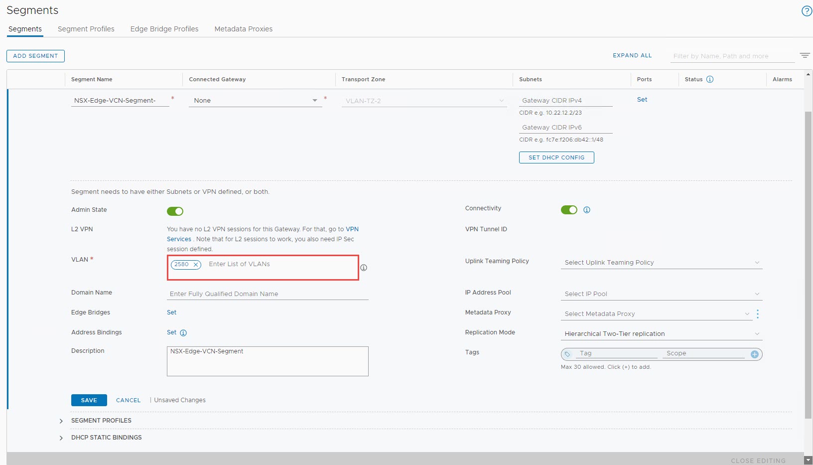
As we are not performing anymore VLAN tagging at the Logical Switch level, we need to edit our VCN Segment to perform VLAN tagging.
- Switch back to Policy Mode by using the toggle on the top-right
- Edit the existing NSX-Edge-VCN-Segment
- In the VLAN section, remove “0” and enter the VLAN Tag of the Uplink1 VLAN from the OCI console, i.e., 2580 and select Save
- This should begin the traffic back to any existing VMs in the overlay segments
- Validate the status before continuing to further sections
The next couple of steps are optional if you’re using the existing Uplink 2 VLAN. They’re only required if you want to create a new VLAN, if the existing Uplink 2 VLAN is already being used for other purposes.
Create a new VLAN in the SDDC VCN
To create a VLAN, navigate to the VCN where SDDC was deployed. Select the appropriate compartment, VCN, and navigate to the VLANs section.
-
Click the Create VLAN button.
-
Validate the compartment and the select VLAN type as regional.
-
Leave the VLAN Tag section empty. OCI assigns a tag during creation of the VLAN.
-
Enter a CIDR range for the VLAN that’s free within the VCN.
-
Select the route table to use for the VLAN. In the following example, I created a route table for VLAN before creating the VLAN. Validate that appropriate route rules are entered for your requirements.
-
Similarly, select a network security group (NSG) for the VLAN and validate that appropriate rules exist.
-
Select Create VLAN to submit the task.
-
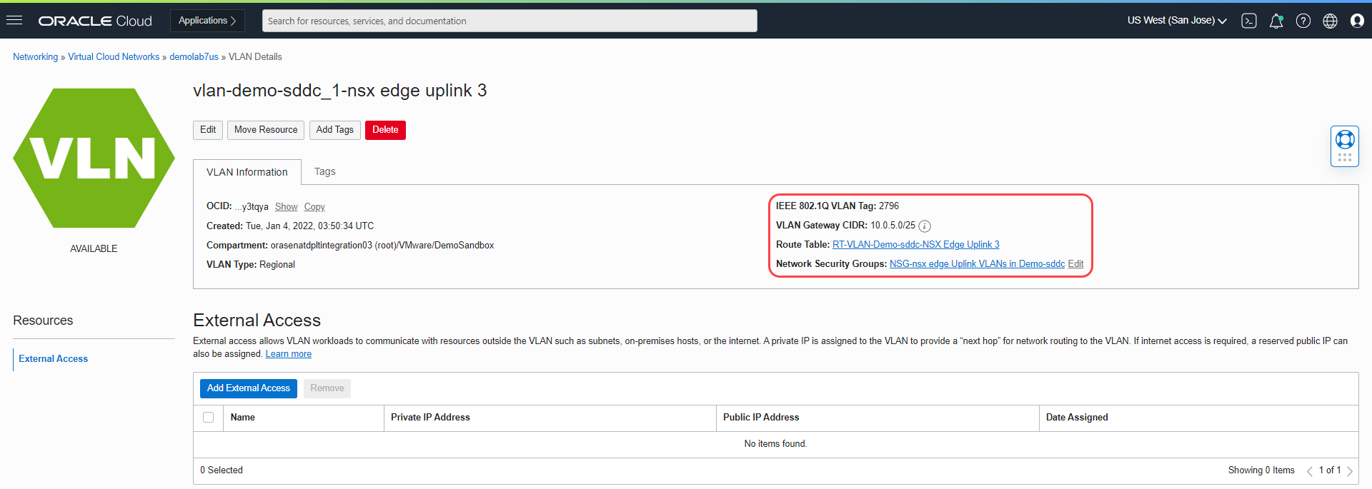
As seen in the following screenshot, the VLAN was created with the tag 2796.
To use the VLAN that we created within the SDDC, we need to first connect the VLAN to the ESXi hosts. One of OCI’s core constructs called isolated network virtualization requires this step.
To attach the VLAN to the ESXi hosts, use the following steps:
-
In the Oracle Cloud Console, navigate to the Instances section under Compute.
-
Attach the VLAN to one ESXi host at a time. Select the first ESXi host in the cluster.
-
Near the bottom-left, select Attached VNICs and then select Create VNIC.
-
To create a VNIC, provide the following details:
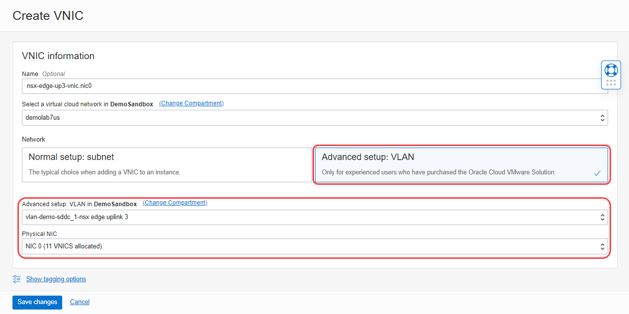
- Select the Advanced setup: VLAN tile to use a VLAN-based connectivity.
-
Select the VLAN we created earlier. Our example uses vlan-demo-sddc_1-nsx edge uplink 3.
-
From the menu, select Physical NIC 0 and click Save changes.
-
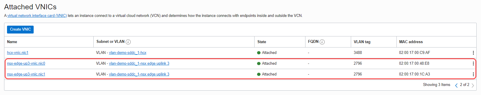
Repeat the steps to create a VNIC on the physical NIC 1.
-
When complete, we have two NICs on the first ESXi host as seen in the following image.
-
Attach the VLAN onto all the other ESXi hosts in the SDDC.
Environment Details
Now that we have created the Uplink3 VLAN, document the required details as shown below which we will use for deploying VRF gateway.
| VCN CIDR Block | 10.0.0.0/16 | |||
| VLAN Details |
||||
| NSX Edge Uplink1 VLAN | CIDR | 10.0.0.128/25 | ||
| VLAN Tag | 3863 | |||
| VLAN Gateway | 10.0.0.129/25 | |||
| NSX Edge Uplink2 VLAN (if using Uplink2 VLAN) |
CIDR | 10.0.1.0/25 | ||
| VLAN Tag | 2103 | |||
| VLAN Gateway | 10.0.1.1/25 | |||
| Three available IPs | 10.0.1.2 | 10.0.1.3 | 10.0.1.4 | |
| NSX Edge Uplink3 VLAN (if using Uplink3 VLAN) |
CIDR | 10.0.5.0/25 | ||
| VLAN Tag | 2796 | |||
| VLAN Gateway | 10.0.5.1/25 | |||
| Three available IPs | 10.0.5.2 | 10.0.5.3 | 10.0.5.4 | |
If you’re using the existing Uplink 2 VLAN, you can skip the previous steps and continue from this section. When creating a VRF gateway, you’re required to provide a high-availability VIP for the gateway. This high-availability VIP is an endpoint in the VLAN that allows routing rules to be associated with in the VCN.
-
Navigate to the VLAN that you’re going to use for VRF gateway (NSX Edge Uplink 3 VLAN in my case).
-
Select Add External Access.
-
For External Access Type, select Route Target Only.
-
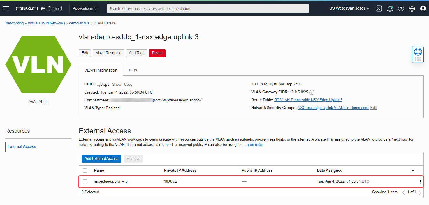
If you want a specific IP, provide a name and IP address in the private IP address section and select Add External Access.
The following screenshot shows a VIP with the private IP address 10.0.5.2.
Before we move onto the next section, let’s document the details of NSX Edge Uplink 3 VLAN, which re required during the creation of the VRF gateways within NSX-T Manager.
-
CIDR range: 10.0.5.0/25
-
Default gateway: 10.0.5.1
-
VLAN tag: 2796
-
VLAN external access endpoint for VRF high-availability VIP: 10.0.5.2
-
Two available IPs in the VLAN for VRF interfaces: 10.0.5.3, 10.0.5.4
Deploying the NSX-T VRF gateway
Log in to the NSX-T Manager. Connect the NSX-T overlay to the OCI underlay infrastructure with the following steps:
-
Create a transport zone profile and push the new profile onto all ESXi hosts in the SDDC.
-
Push the new transport zone profile onto all the existing NSX edges.
-
Create a VLAN backed segment.
-
Update the existing logical switch to allow the new VLAN tag.
-
Create a VRF on the existing tier-0 gateway.
-
Create a tier-1 gateway and attach it to the VRF gateway.
-
Create an overlay segment on tier-1 gateway with appropriate NAT rules.
Now, we can see each of these steps in depth and configure a VRF gateway.
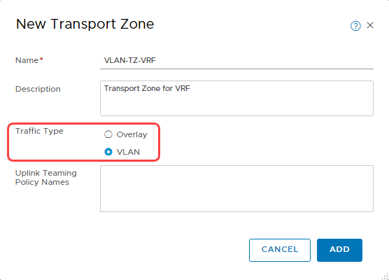
Create a transport zone
-
For a detailed explanation, refer to Create Transport Zone.
-
When creating a transport zone, select the traffic type as VLAN, as seen in the following screenshot.
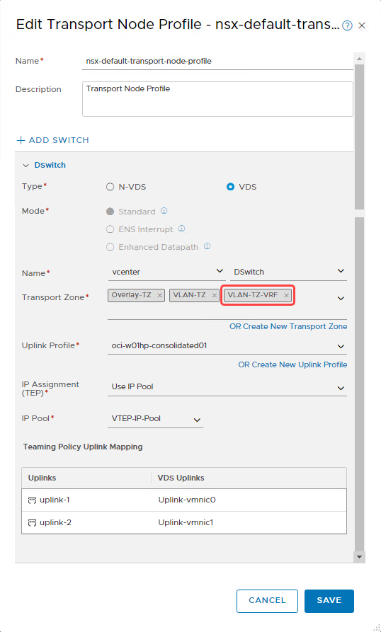
Update transport node profile
For a detailed explanation, refer to Transport Node Profile. To push the new VLAN Transport Zone to all ESXi Hosts, use the following steps:
-
Navigate to transport node profile section.
-
Edit the existing nsx-default-transport-node-profile.
-
Select the transport zone that we created earlier. The following screenshot shows that I selected VLAN-TZ-VRF in the transport zone section.
-
Select Save to push the configuration onto all ESXi hosts in the cluster.
Push the transport zone to NSX Edge nodes
For more details, refer to the NSX Edge Transport Node. To update existing NSX Edge node, use the following steps:
-
Navigate to edge transport nodes in the Nodes section.
-
Select the existing nsx-edge-01 and click Edit.
-
In the Transport Zone section, under oci-w01-vds02, select the transport zone that we created earlier from the menu, as seen in the following image.
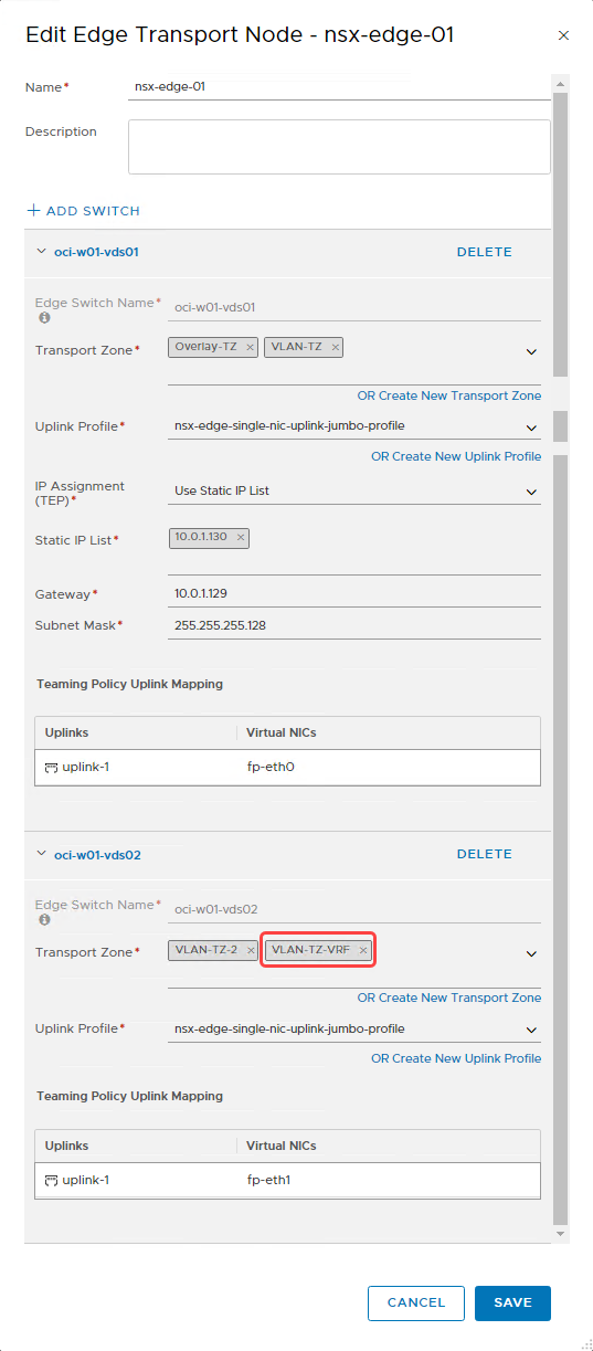
-
Select Save to push the configuration.
- Push the configuration to the second NSX Edge node, nsx-edge-02, which is attached to the tier-0 gateway.
Create a VLAN-backed segment for uplink3
Let’s create a VLAN-backed segment for the transport zone we created earlier. To learn more about VLAN-backed segments, refer to Add a Segment. When adding a VLAN-backed segment, I choose the inputs for the fields as seen in the following image.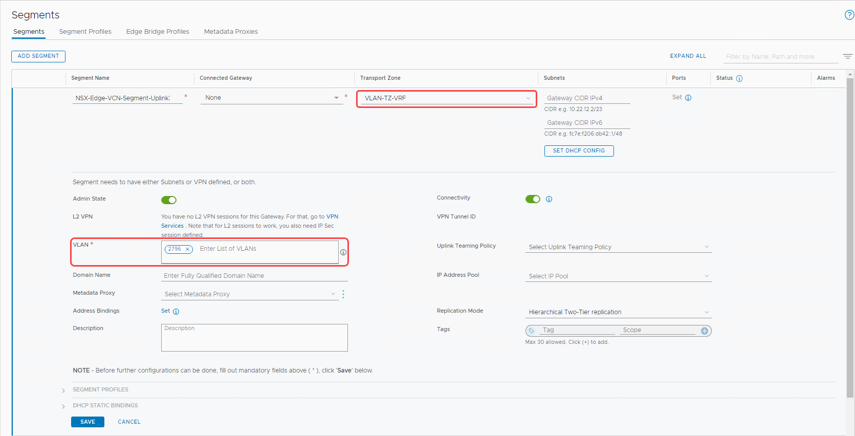
-
Transport zone: The transport zone we created earlier, VLAN-TZ-VRF.
-
In the VLAN section, enter the VLAN tag on the NSX Edge uplink 3 VLAN created in OCI, 2796.
-
Select Save to create the segment.
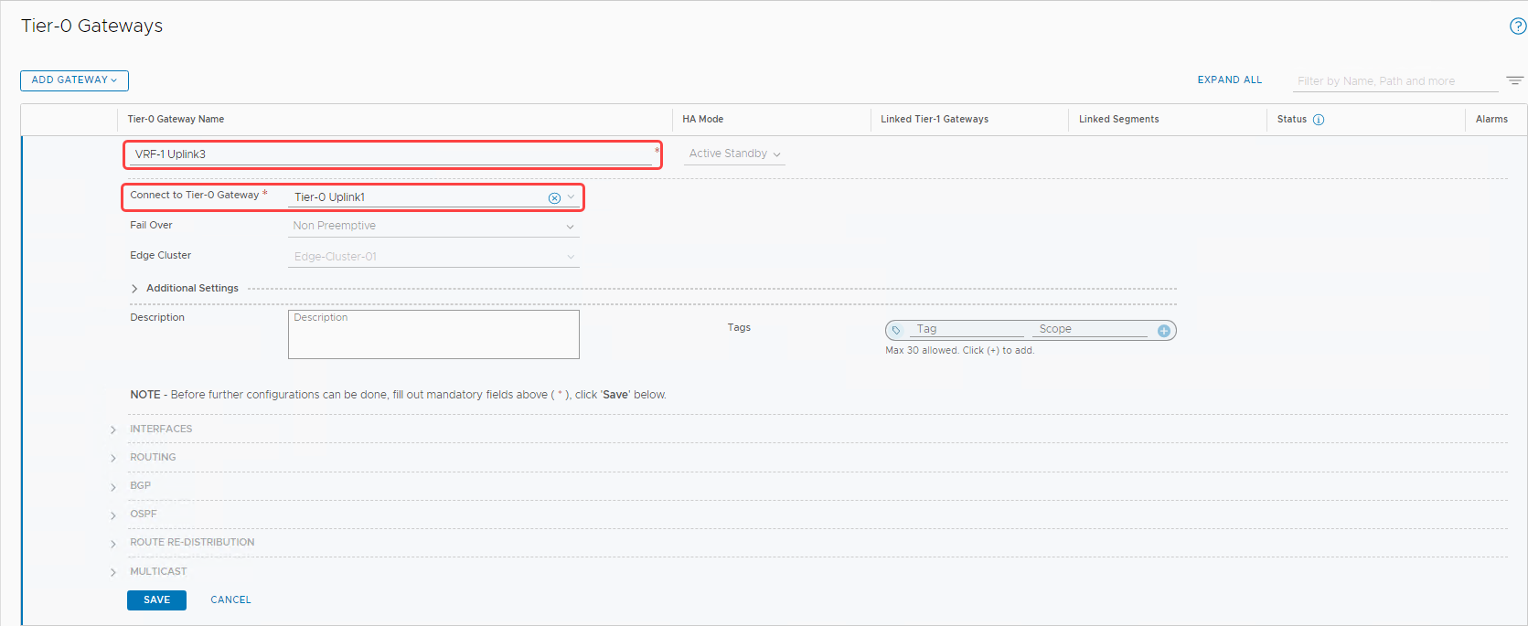
Create VRF on an existing tier-0 gateway
To learn more about VRF gateways, refer to Add a VRF Gateway.
-
In the Networking tab, switch to Policy Mode.
-
Select Tier-0 Gateways in the left menu.
-
Click the Add Gateway button, and from the menu, select VRF.
-
Enter the name, select the existing tier-0 from the menu, and click Save.
-
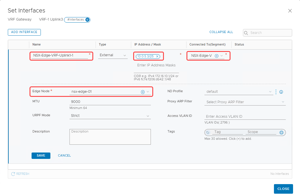
Continue to edit the VRF gateway. Expand the Interfaces section and click Set to add interfaces.
-
Add the first interface for nsx-edge-01 with the following details:
-
Name: NSX-Edge-VRF-Uplink1-1
-
IP address and mask: 10.0.5.3/25
-
Connected to (Segment): NSX-Edge-VCN-segment-uplink3 (The VLAN-backed segment that we created earlier)
-
Edge node: Select nsx-edge-01 from the menu and select Save.
-
-
Similarly, create a second interface on the nsx-edge-02 node.
-
Name: NSX-Edge-VRF-Uplink1-2
-
IP address and mask: 10.0.5.4/25
-
Connected to (Segment): NSX-Edge-VCN-segment-uplink3 (The VLAN-backed segment that we created earlier)
-
Edge node: Select nsx-edge-02 from the menu and click Save.
-
We now have two interfaces added to the VRF gateway as seen in the following screenshot. Select Set across the high-availability VIP configuration.
Now continue to edit the VRF gateway to configure the high-availability VIP for the interfaces.
-
Select Set across the high-availability VIP configuration.
-
Enter the high-availability VIP address, 10.0.5.2/25.
-
Select the interfaces that we created in the previous step, as seen in the following image:

-
Select Add and Apply to complete high-availability VIP configuration.
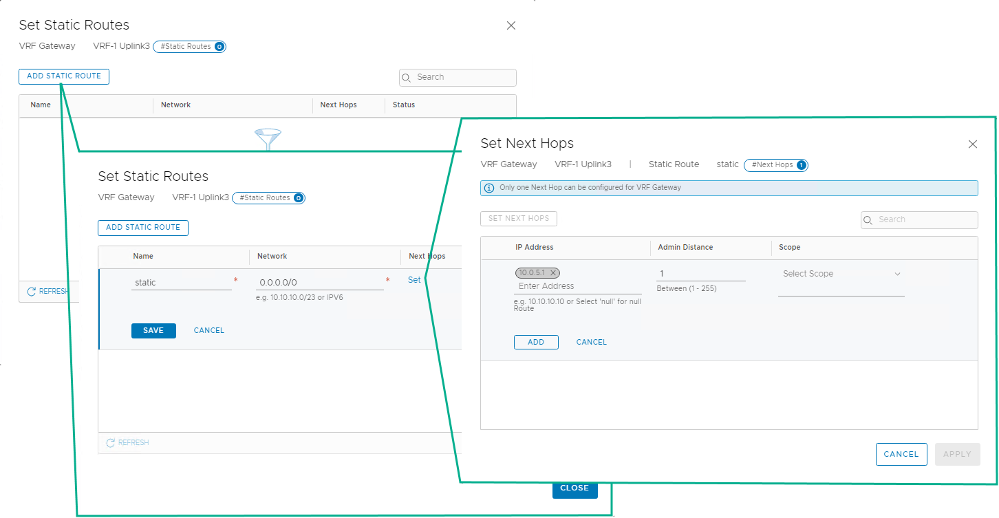
When the interfaces are created, a default static route needs to be configured for the VRF. To set the static route, use the following steps:
-
Continue to edit the VRF and in the Routing section, select Set for the static routes.
-
Select Add Static Route.
-
Provide a name, and for the network, enter 0.0.0.0/0.
-
For the next hops, select Set. Provide the IP address of the default gateway of the Uplink 3 VLAN and the admin distance as 1.
-
To complete the VRF editing, click Add, Save, and then Close Editing.
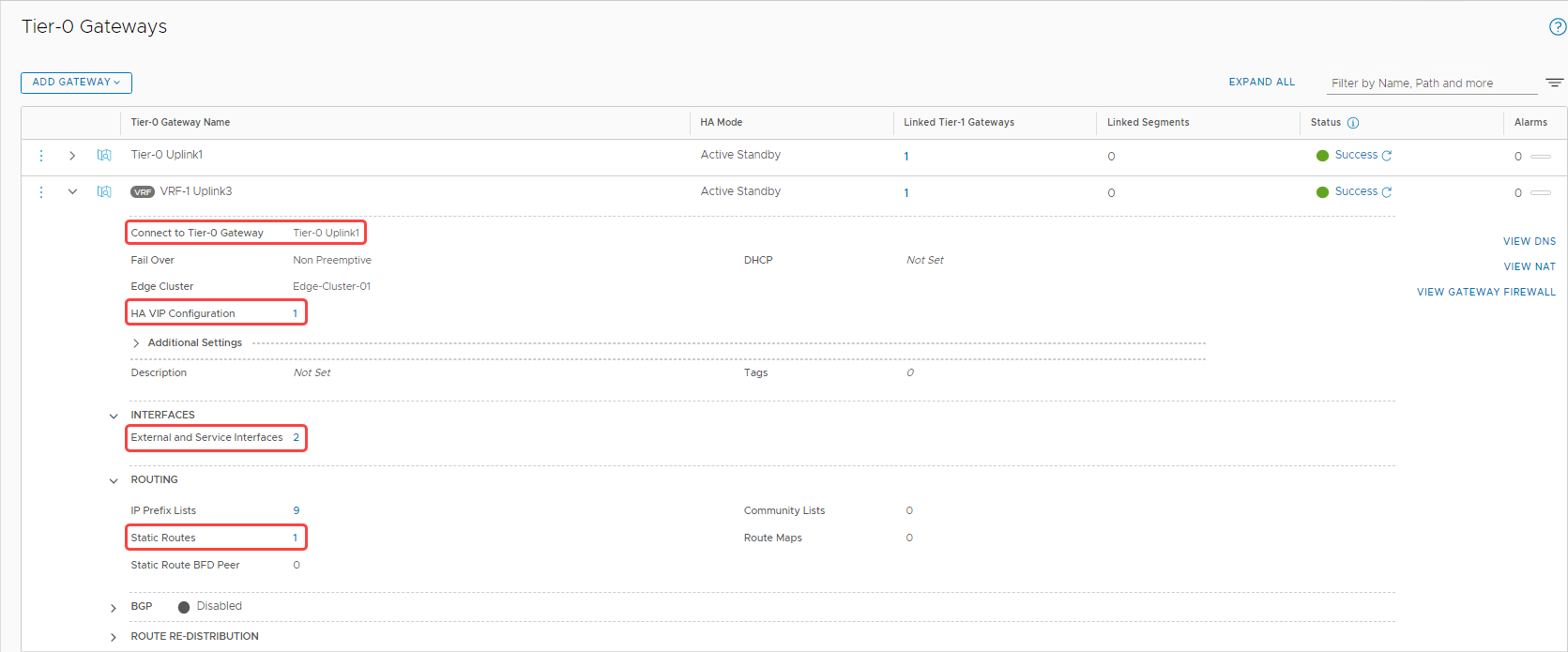
Let’s review the configurations on the VRF gateway. The following screenshot shows the following details:
-
The VRF gateway is connected to the same tier-0 gateway.
-
We have two configured interfaces.
-
We have one high-availability VIP configured for the interfaces.
-
We configured a static route.
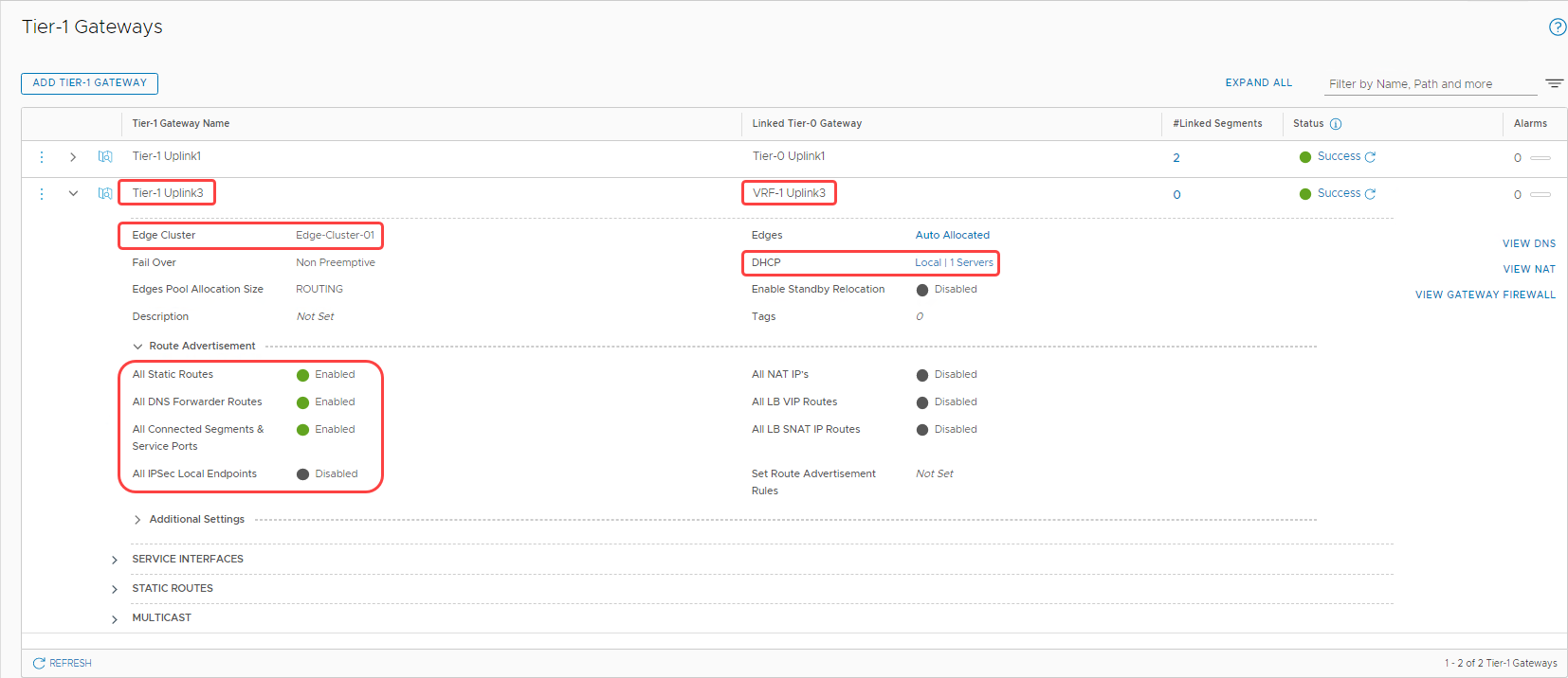
Create tier-1 gateway
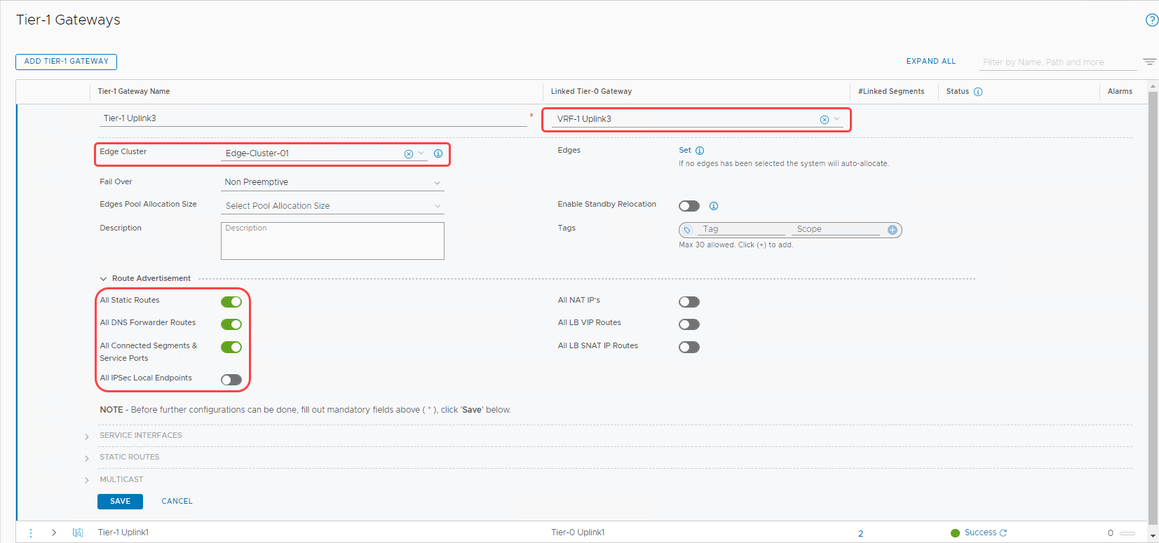
Let’s add a Tier-1 gateway and attach it with the VRF gateway that we created in the earlier section.
-
In the Networking section, navigate to Tier-1 Gateways and select Add Tier-1 Gateway.
-
Provide a name and select the VRF gateway under Linked Tier-0 Gateway.
-
Select Edge-Cluster-01 from the menu.
-
Under Route Advertisement, make the switches match the following image.
-
To finish the configuration, click Save.
Configuring DHCP for tier-1 gateway (Optional)
If you want to use DHCP on the overlay segments connected to this tier-1 gateway, you need to configure DHCP server details.
-
Edit the tier-1 gateway that was created in the earlier step.
-
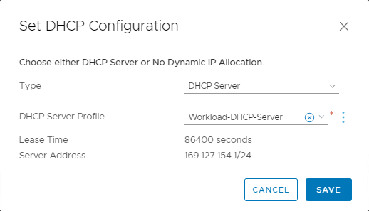
In the DHCP section, select Set DHCP Configuration.
-
For type, select DHCP Server.
-
For DHCP server profile, select Workload-DHCP-Server. The automation when the VMware Solution SDDC was initially deployed created this option. Then click Save.
The following screenshot shows the final configuration of the tier-1 gateway:
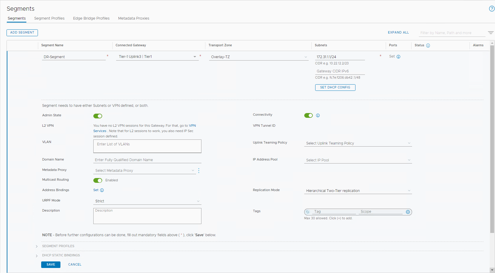
Add an overlay segment
Follow the VMware document to Add an Overlay Segment and connect it to the Uplink3 tier-1 gateway. The following image shows the created segment named DR-Segment.
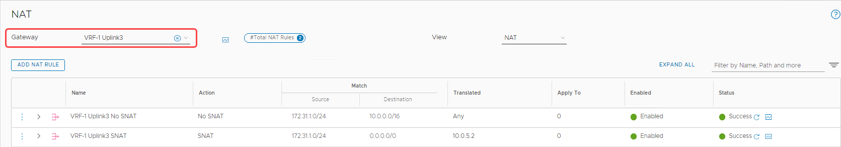
Configure NAT rules
For all the workload VMs trying to reach the internet, the traffic needs to traverse through one of the OCI gateways, such as an NAT gateway or an internet gateway. By default, OCI doesn’t know how to route back to the overlay NSX segments. For any traffic leaving the OCI VCN that sends a response, if the response is for a non-VCN related destination, the traffic is dropped.
So, for any traffic trying to reach the internet, we configure a source NAT (SNAT), which the edge VIP (10.0.5.2) translates. Similarly, for all the traffic between OCI and the overlay segment, we configure a no-source NAT (No SNAT). To configure the NAT on the VRF gateway, follow the Configure NAT on a Gateway documentation. In the following image, I configured two NAT rules: A No SNAT rule to VCN, and a SNAT rule to anything else through the NSX Edge Uplink 3 VIP.
Validation
To summarize the configuration, the network topology shows a true multitenancy deployed within NSX-T, without having to deploy any extra NSX Edge resources.
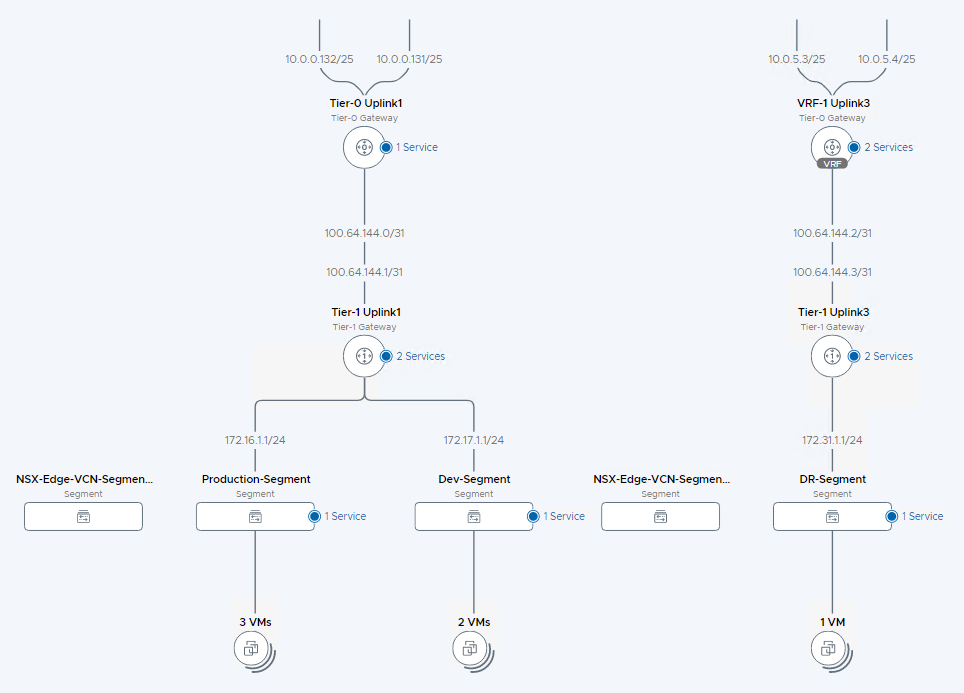
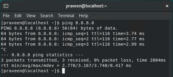
To validate that the configuration works as expected, we have a VM on the DR-Segment, which can reach internet successfully.
Conclusion
VRF gateways eliminate the need to deploy separate NSX edge appliances, while providing as much control for configuring a true multitenancy environment within NSX-T. You can use this architecture for various use cases, such as hosting demilitarized workloads or when multi-tenancy configurations are required within the same SDDC. You can use the same process in scenarios where the NSX-T throughput needs to be increased for north-south traffic.
This blog proves that when NSX 3.x is coupled with Oracle Cloud Infrastructure’s networking capabilities, customers can easily scale out their NSX-T environments without adding any management overhead. Give this process a try, and if you want to learn more about Oracle Cloud VMware Solution, contact us.