Co-authored by Vinay Rao, Principal Solutions Architect
Oracle and VMware have developed a fully certified and supported software-defined data center (SDDC) solution called Oracle Cloud VMware Solution. This solution is a dedicated, cloud-native VMware-based environment that enables enterprises to easily move their production VMware workloads to Oracle Cloud Infrastructure (OCI). Unique to Oracle Cloud VMware Solution, customers have complete access and control of their VMware environment with no limits to run production enterprise applications in the cloud without compromise.
Recently, one of our customers had a requirement to create a demilitarized zone (DMZ) environment within NSX-T and to not share any of the tier-0 and tier-1 gateways. While a few methods can configure multitenancy within OCVS, in this blog, we provide step-by-step guidance to deploy separate tier-0 and tier-1 gateways within your NSX-T data center to separate segments to securely host both internal and DMZ workloads.
Because VMware Solution promises its customers complete control and flexibility on their SDDCs, you can deploy an extra NSX infrastructure to separate the NSX microsegments, while keeping security in mind. In an other blog we discussed deploying VRF Gateway to achieve multitenancy where the customers don’t require extra NSX infrastructure, which is available from NSX-T 3.0.
What to expect
Oracle Cloud VMware Solution is a service based on well-known VMware virtualization components such as vSphere, NSX, and vSAN. Like server virtualization, NSX provides network virtualization to programmatically create and manage virtual networks. During the deployment of VMware Solution SDDC, we automate the deployment of NSX Edge uplink 1 VLAN and its related infrastructure within NSX. You can then create several NSX segments to separate your workloads based on their infrastructure needs, such as application isolation and zero-trust. To learn more, see micro-segmentation using NSX in the documentation.
For each VLAN within the SDDC, we can route traffic to the internet through a NAT gateway or an internet gateway. To solve the use case of having a DMZ within NSX-T, while maintaining the operation of other microsegments and keeping security in mind, we recommend that you deploy separate NSX infrastructure for internet-facing virtual machines (VMs) and non-internet-facing VMs, as shown in the following graphic.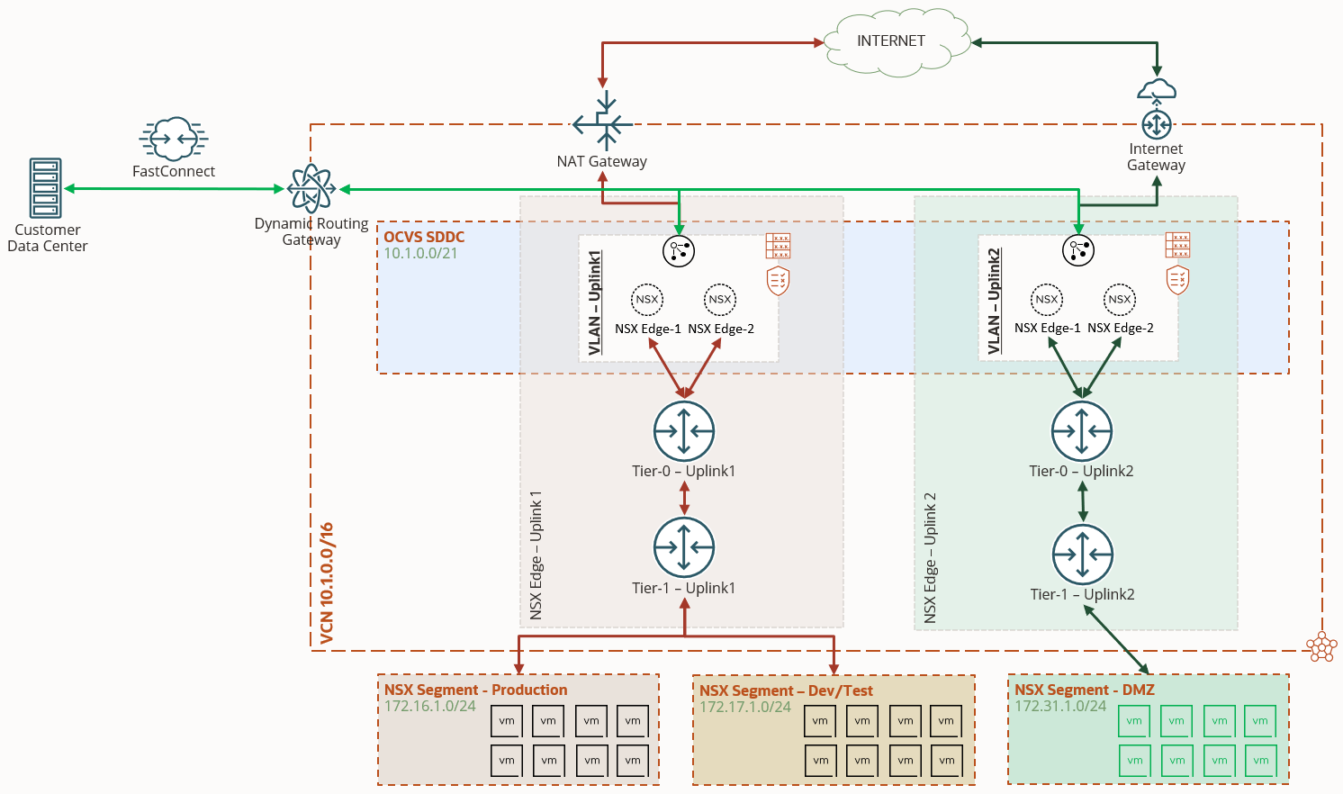
The following steps help you create separate NSX infrastructure for uplink 2 VLAN:
-
Create uplink profiles, transport zone, and a logical switch.
-
Create NSX Edge nodes.
-
Create tier-0 and tier-1 routing infrastructure for uplink 2 VLAN.
-
Create an NSX segment and attach it to the new tier-1 gateway.
-
Add appropriate NAT entries in the NSX Manager and route rules in OCI uplink 2 VLAN.
Steps to deploy separate NSX-T infrastructure for uplink 2 VLAN
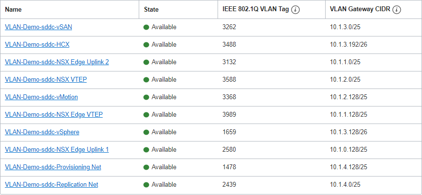
Before we begin, let’s look at the VLANs for the SDDC and plan the network details. The following image shows a snippet of the VLANs in our lab environment.
Let’s also document the details as shown in the following table:
| Required details for configuration | ||||
|---|---|---|---|---|
| VCN | CIDR | 10.1.0.0/16 | ||
| vSphere VLAN | CIDR | 10.1.3.128/25 | ||
| Two available IPs | 10.1.3.138 | 10.1.3.139 | ||
| NSX Edge Uplink 2 VLAN | CIDR | 10.1.1.0/25 | ||
| VLAN Tag | 3132 | |||
| Three available IPs | 10.1.1.2 | 10.1.1.3 | 10.1.1.4 | |
| NSX Edge VTEP | CIDR | 10.1.1.128/25 | ||
| Two available IPs | 10.1.1.132 | 10.1.1.133 | ||
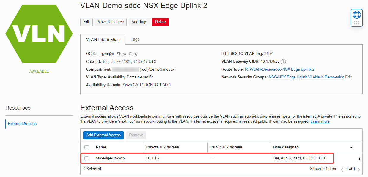
Add an external access IP for the NSX Edge high availability virtual IP
In the OCI Console, navigate to uplink 2 VLAN and add an external access IP for the high availability virtual IP (VIP).
Next, log in to the NSX Manager to start the configuration.
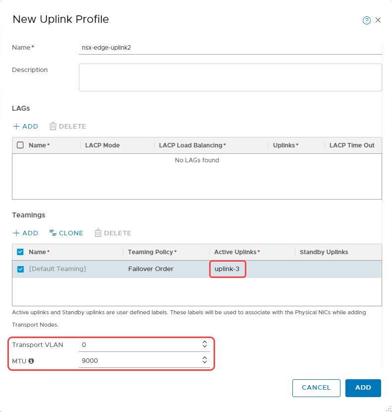
Create an uplink profile for uplink 2 VLAN
For a step-by-step process, see Create an Uplink Profile.
When creating the uplink profile, under the Active Uplinks in Teamings section, add uplink-3. For Transport VLAN, enter 0. For MTU, enter 9000.
The following screenshot shows the parameters that we used to create an uplink profile:
Create a transport zone and prepare transport nodes
For a step-by-step process, see Create Transport Zones in the documentation.
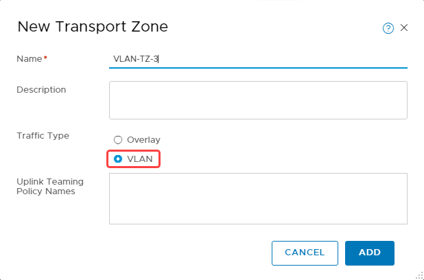
-
When creating a transport zone, select the traffic type as VLAN.
-
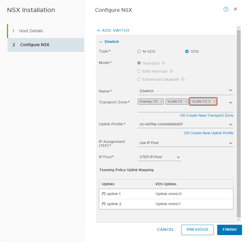
After a transport zone is created, we can configure each ESXi host or transport node to create the zone. For details, see Prepare ESXi Cluster as Transport Nodes.
-
Navigate to the Host Transport Node section under Fabric–Nodes. Select one ESXi host at a time and select Configure NSX.
-
Select Next to navigate to the Configure NSX tab and for Transport Zone, select VLAN-TZ-3. Click Finish.
-
Continue to Configure NSX on all the transport nodes and confirm that the NSX configuration status shows as success.
Create a VLAN-backed segment
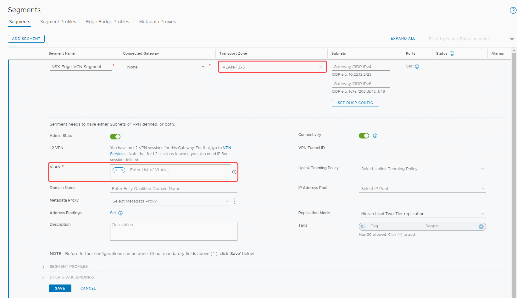
We can add two kinds of segments: VLAN-backed or overlay-backed. In this section, we create a VLAN-backed segment. For details, see Add a Segment.
When creating a VLAN-backed segment, select the transport one) that we created earlier (VLAN-TZ-3 and enter the VLAN as 0. The following screenshot shows the details of the VLAN-backed segment that we created.
Create a logical switch
-
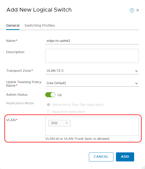
Switch to Manager mode to create a Logical Switch.
-
Select the VLAN-TZ-3 transport zone.
-
Enter the VLAN tag of Uplink 2 VLAN, which we captured earlier.
The following screenshot shows the configuration of the logical switch.
Create NSX Edge transport nodes
We add a pair of NSX Edge transport nodes dedicated for uplink 2 VLAN. For detailed steps, see Create an NSX Edge Transport Node.
-
In the workflow of Adding an Edge Node, we recommend choosing a large form factor but choose the node size that fits your requirements.
-
In the Credentials section, provide the passwords for CLI, root, and audit users and enable the Allow SSH Login toggle.
-
In the Configure Deployment tab, select the following parameter:
-
Compute manager: vCenter
-
Cluster: oci01-w01-consolidated01
-
Resource pool: Management
-
Datastore: vsanDatastore
-
-
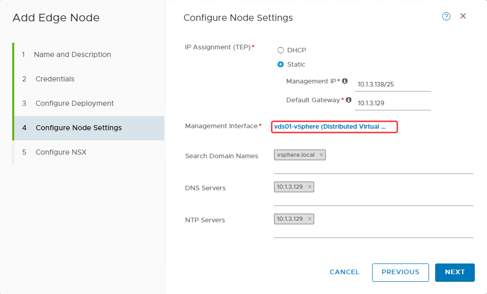
To configure node settings, use the following parameters:
-
Choose the IP Assignment (TEP): Static
-
Enter the management IP and default gateway as planned earlier from vSphere VLAN.
-
Enter the remaining details as shown and click Next.
-
-
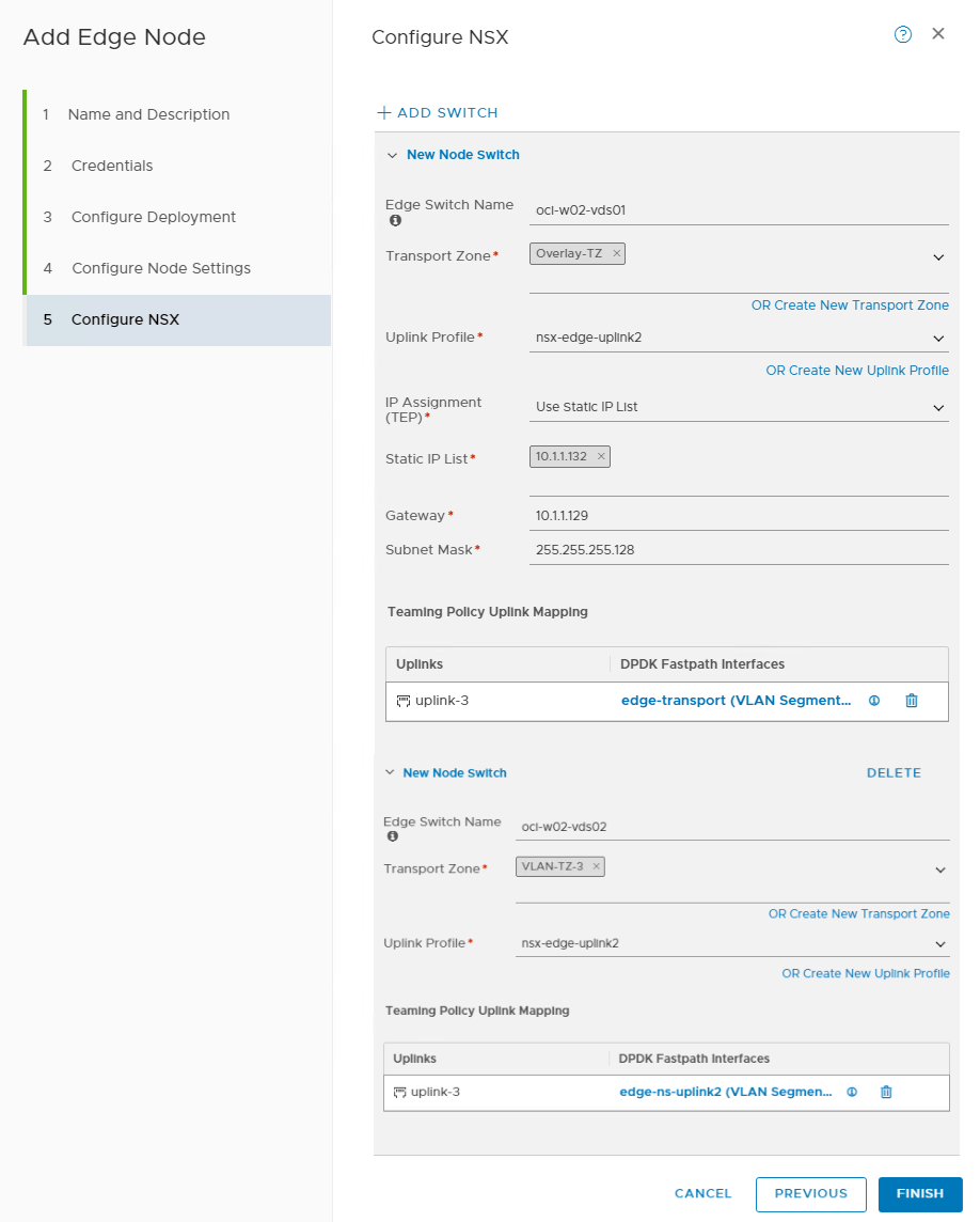
In the Configure NSX tab, add a node switch and provide the following details:
-
Transport zone: Overlay-TZ
-
Uplink profile: nsx-edge-uplink2
-
IP assignment (TEP): Use static IP list
-
Provide static IP and other details
-
For uplink 3, select edge-transport.
-
-
Add a second node switch and provide the following details:
-
Transport zone: VLAN-TZ-3
-
Uplink profile: nsx-edge-uplink2
-
Select edge-ns-uplink2 for uplink 3
-
-
Deploy another NSX Edge node.
Create an NSX Edge cluster
We create a NSX Edge Cluster for the NSX Edges created in the earlier section. Refer to the documentation for details on creating NSX Edge Cluster.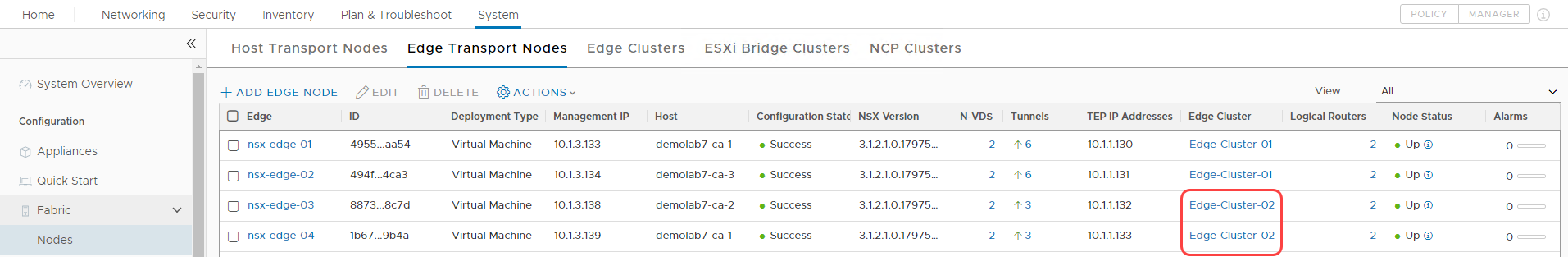
Tier-0 gateway
For a detailed process, see Add a Tier-0 gateway in the documentation.
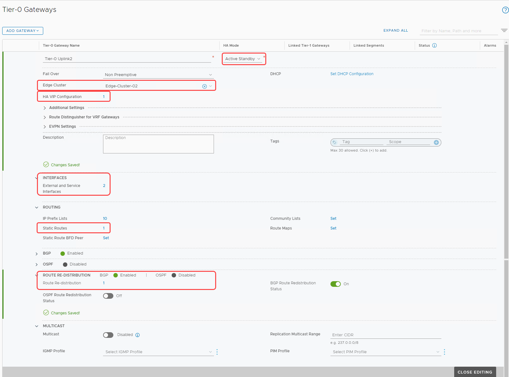
Create a tier-0 gateway with details shown in the following image. Save the settings and continue to edit the gateway.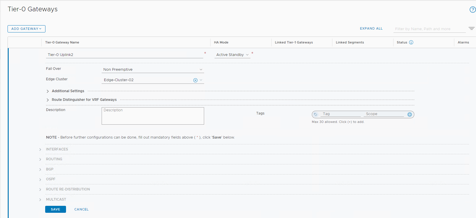
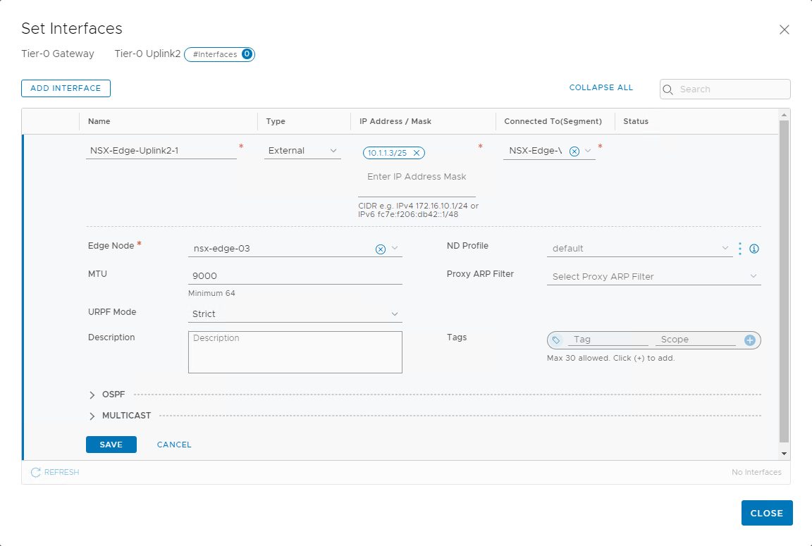
Add interfaces to the tier-0 gateway
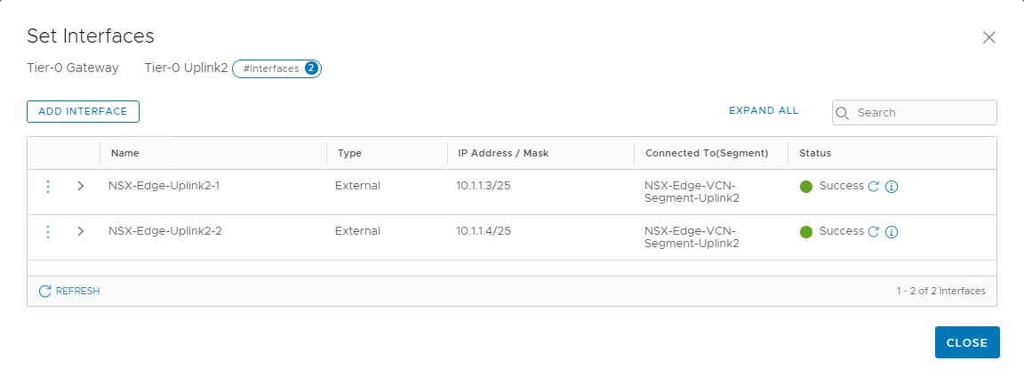
Expand the Interfaces section and click Add Interfaces. In the following image, we can see the IP address from the uplink 2 VLAN added to the nsx-edge-03 node.
Similarly, create a second interface for the nsx-edge-04 node and validate that the status shows success.
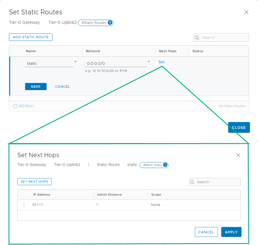
Set static routes
Continue to edit the tier-0 gateway to add static routes in the Routing section. We want all traffic to take the next hop as the default gateway.
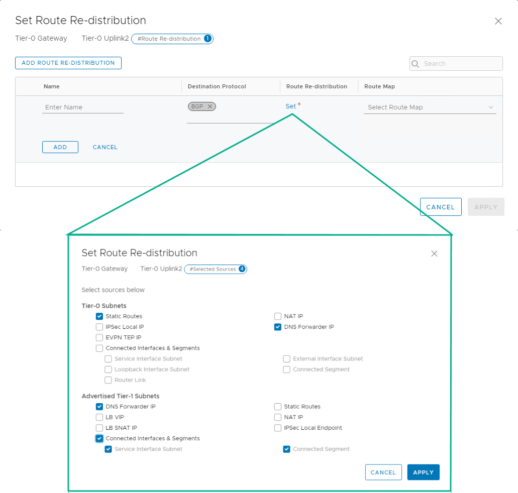
Add route redistribution
Add a route redistribution, as shown in the following image.
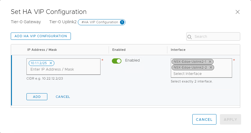
Configure high availability VIP
Now, let’s configure the high availability virtual IP for the tier-0 gateway by clicking Set beside the HA VIP Configuration button. In the following image, we can see that we’re inputting the VIP as the external access IP, created in OCI Console in the earlier sections. Configure the other settings as shown.
When all the settings are configured, the tier-0 gateway looks like the following screenshot. Validate and close the editing window.
Tier-1 gateway
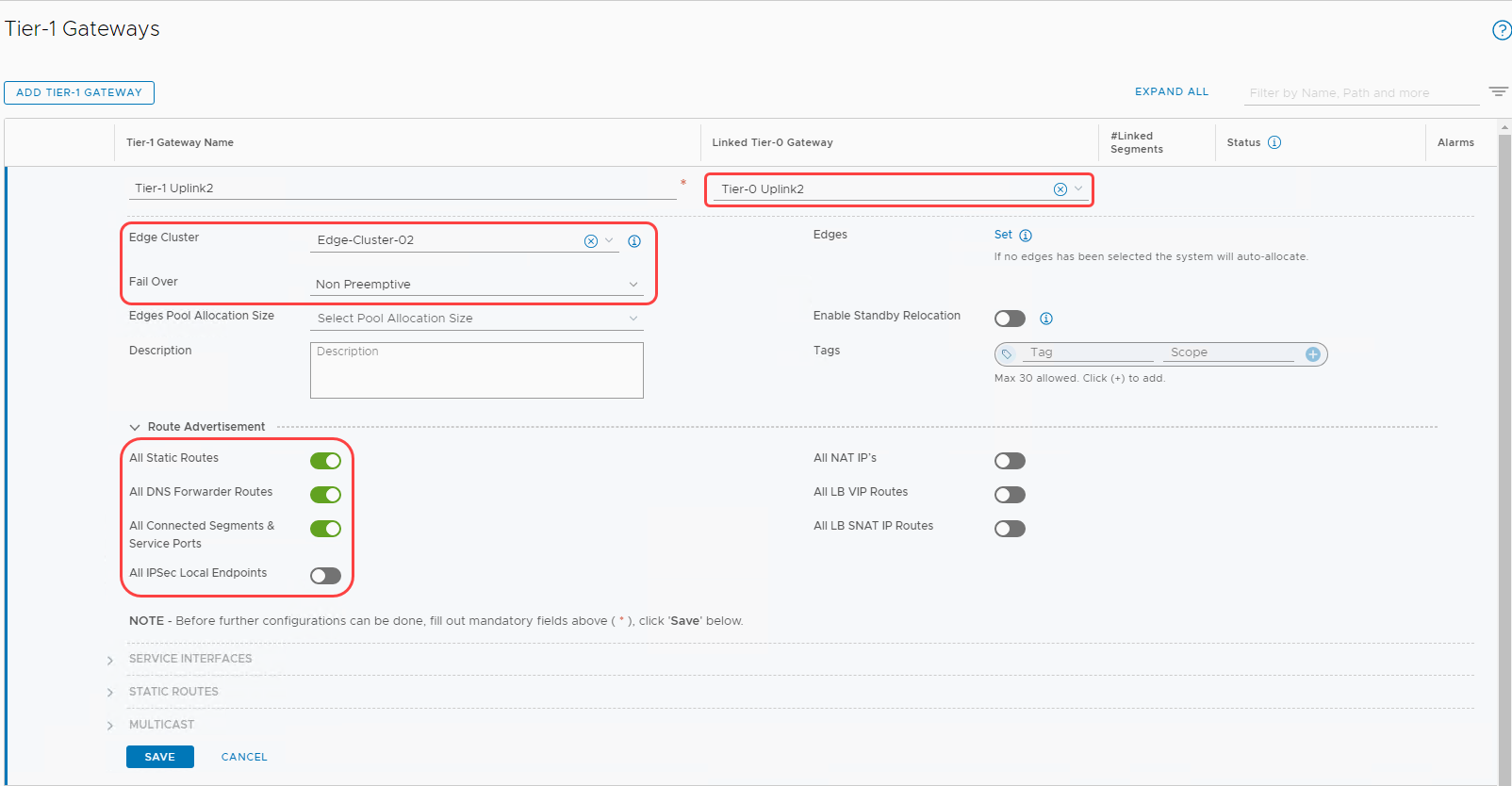
For a detailed process, refer to Add a Tier-1 Gateway in the documentation. Edit the configuration of the tier-1 gateway to match the following image.
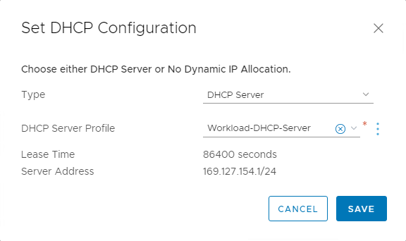
Set DHCP on tier-1 gateway
Edit the tier-1 gateway and select Set DHCP Configuration to associate a DHCP server. Then select the existing DHCP server as shown.
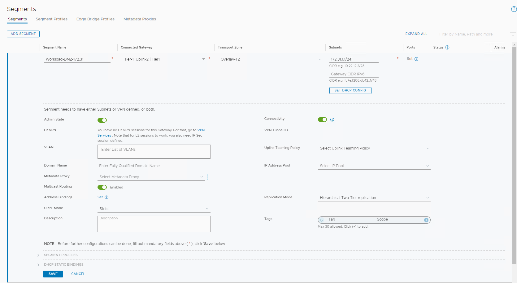
Configure overlay segment for DMZ
Overlay segment
For detailed instructions on how to add an overlay-backed segment, see Add a Segment. Follow the details in the following image:
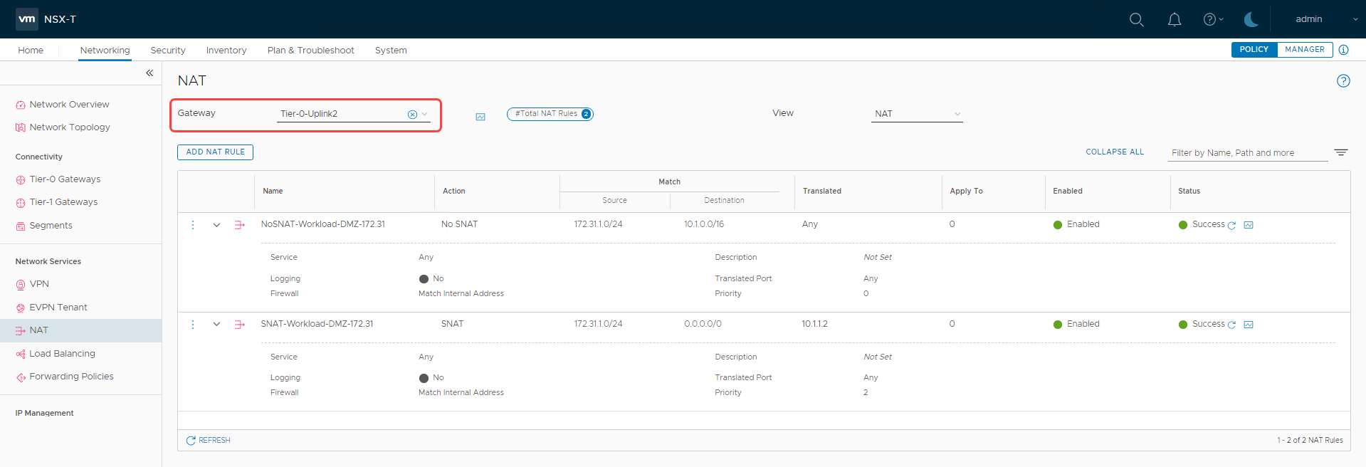
NAT rules
Add appropriate NAT rules to the uplink 2 tier-0 gateway as shown in the following image:
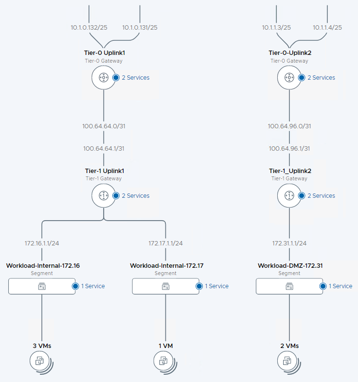
Deploy virtual machines in the DMZ segment and validate connectivity. Finally, let’s view the network topology to validate the high-level architecture. In the following architecture, we can see that we’ve achieved an independent DMZ environment within NSX-T.
Try it for yourself!
You can achieve multitenancy within NSX-T in a few ways. You can easily deploy separate NSX infrastructure for a true autonomous DMZ environment as discussed in this blog. Introduced in NSX-T 3.0 is a concept of VRF gateways, which allows you to achieve multitenancy by sharing the NSX edge infrastructure, read through this blog to understand how VRF can be configured within OCVS.
In another blog, we discuss steps to achieve multitenancy using VRF. Upon configuring multitenancy, you can securely deploy both internal and DMZ workloads within OCVS. We recommend that you use such architectures when assigning public IPs to guest VMs for your DMZ workloads, which provide a true zero-trust isolated NSX environment.
Get started with Oracle Cloud VMware Solution and learn more about our solution.