Coauthored by Javier Ramirez, principal cloud architect
This blog covers a new feature introduced by OCI: Layer 2 networking for VLANs within your virtual cloud networks (VCNs). Today, Fortinet’s FortiGate Firewall high availability cluster requires creating an external SDN connector, a dynamic group, and policies to support high availability configuration. But you don’t need that using this feature. In this case, you can use OCI Layer 2 Networking feature to support the high availability cluster, like how you deploy it on on-premises.
This feature is not generally available yet, and some options might not be available. If you have a use case, work with your technical or partner team to get your tenancy listed to use this feature. Although this blog showcases OCI Layer 2 networking support with Fortinet partner as an example, this feature works in tandem with other third-party appliances. Contact the vendor to ensure that its product works with OCI Layer 2 Networking and is supported by the vendor.
Use case
OCI Layer 2 Networking gives us the simplicity of configuring high availability use case to support OCI workload traffic from VCNs and inspect traffic using firewalls. You can use the OCI Layer 2 Networking feature to assign firewall interfaces to Layer 2 VLANs instead of subnets. In this use case, you send traffic between spoke VCNs and inspect it with FortiGate firewalls.
Prerequisites
- An Oracle Cloud account. If you don’t have an account, you can sign up for an Oracle Cloud Free Tier account.
- A working hub and spoke network topology
- A working FortiGate firewall VM high availability cluster in your hub VCN. You can use Oracle Cloud Marketplace to deploy FortiGate firewall.
- You can also follow this workshop to get familiar yourself with Fortinet’s partner solution.
- Web application virtual machines (VMs) running Apache service on Port 80 are optional.
Topology
You can refer to the following topology to support this use case:
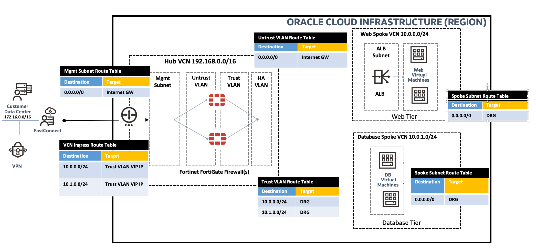
Figure 1: Use case network topology
OCI doesn’t currently support creating a virtual machine with its primary interface, virtual network interface card (VNIC), on an OCI Layer 2 Network. So, we’ve used the management subnet to deploy the firewalls, and the primary interface is attached to subnets, while the others are attached to Layer 2 VLANs.
Configuration
You can follow this section to add the required minimum configuration on FortiGate VM and OCI to integrate with the dynamic routing gateway (DRG). For more configurations, follow the official guide.
Layer 2 VLANs
Create the Layer 2 VLANs within your firewall VCN (the hub VCN), so that the firewall’s interfaces can be created in the VLANs. You can create Layer 2 VLANs using the OCI Console by navigating to Virtual Cloud Networks, Virtual Cloud Network Details, and selecting Resources. To support our use case topology, we create three VLANs within the hub VCN as regional VLANs, which we recommend to support resiliency. VLANs only support network security groups (NSGs) because they don’t support security lists.

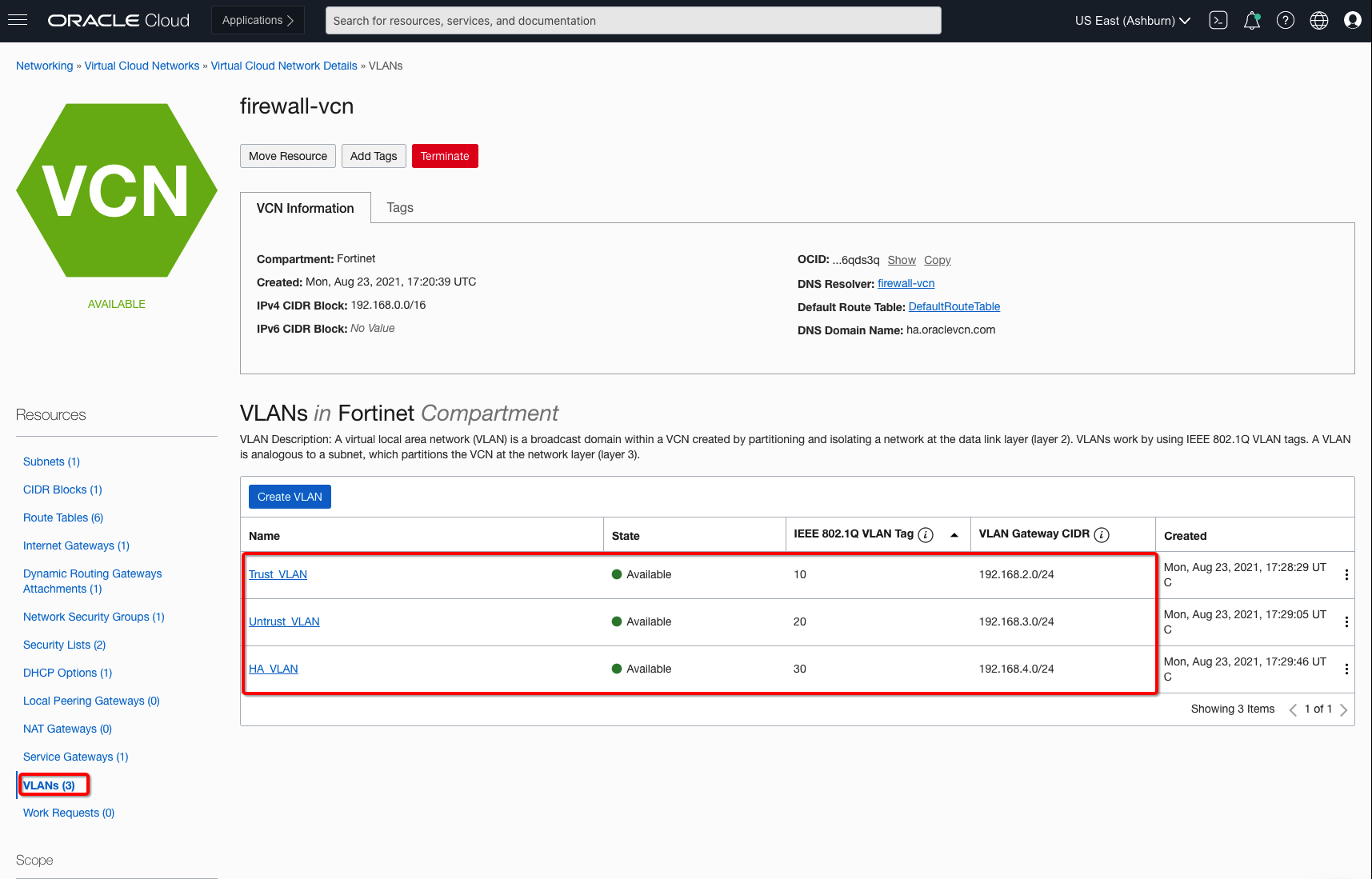
Figure 2: Layer 2 VLANs on the hub firewall VCN
Next, you need to deploy two FortiGate firewall instances using OCI Marketplace. Their primary interfaces are attached to the management subnet.
Fortinet FortiGate firewalls
In the hub VCN, deploy the FortiGate firewall as bring-your-own-license (BYOL) or paid VM listing from OCI Marketplace. You can follow the workshop link to get yourself familiar with the partner solution. When your firewall VMs are up, create three more VNICs (trust, untrust, and high availability) for each firewall and deploy them on the Layer 2 VLANs for the shared use case topology.
When the VNICs are set up, reboot the VM, log into your FortiGate firewall VMs, and configure the interfaces, which can also be referred from workshop. The example uses the following interface configuration for the VMs in the Oracle Console. To support the traffic, use the following minimum steps:
- Assign required external access to use Layer 2 VLANs private or public IP addresses.
- Open the required security policies to support traffic.
- Add the correct routes per use case topology.
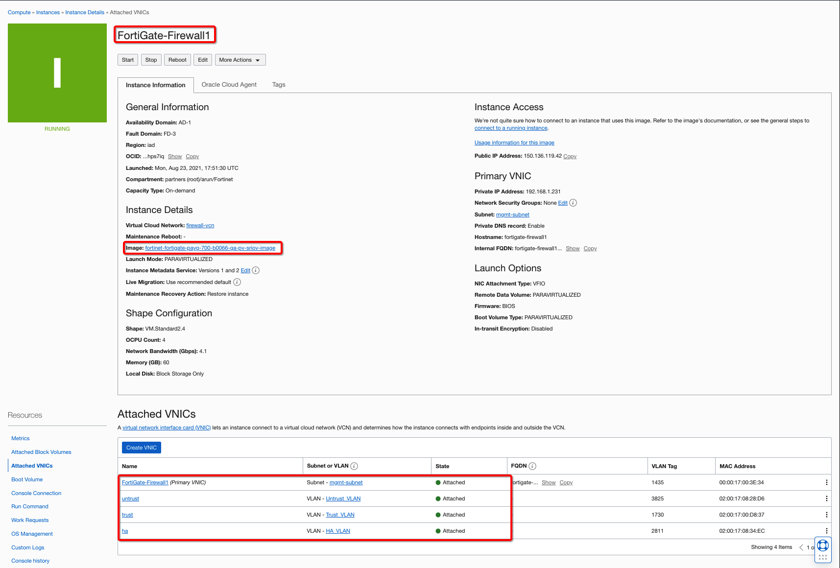
Figure 3: FortiGate primary firewall instance and interfaces
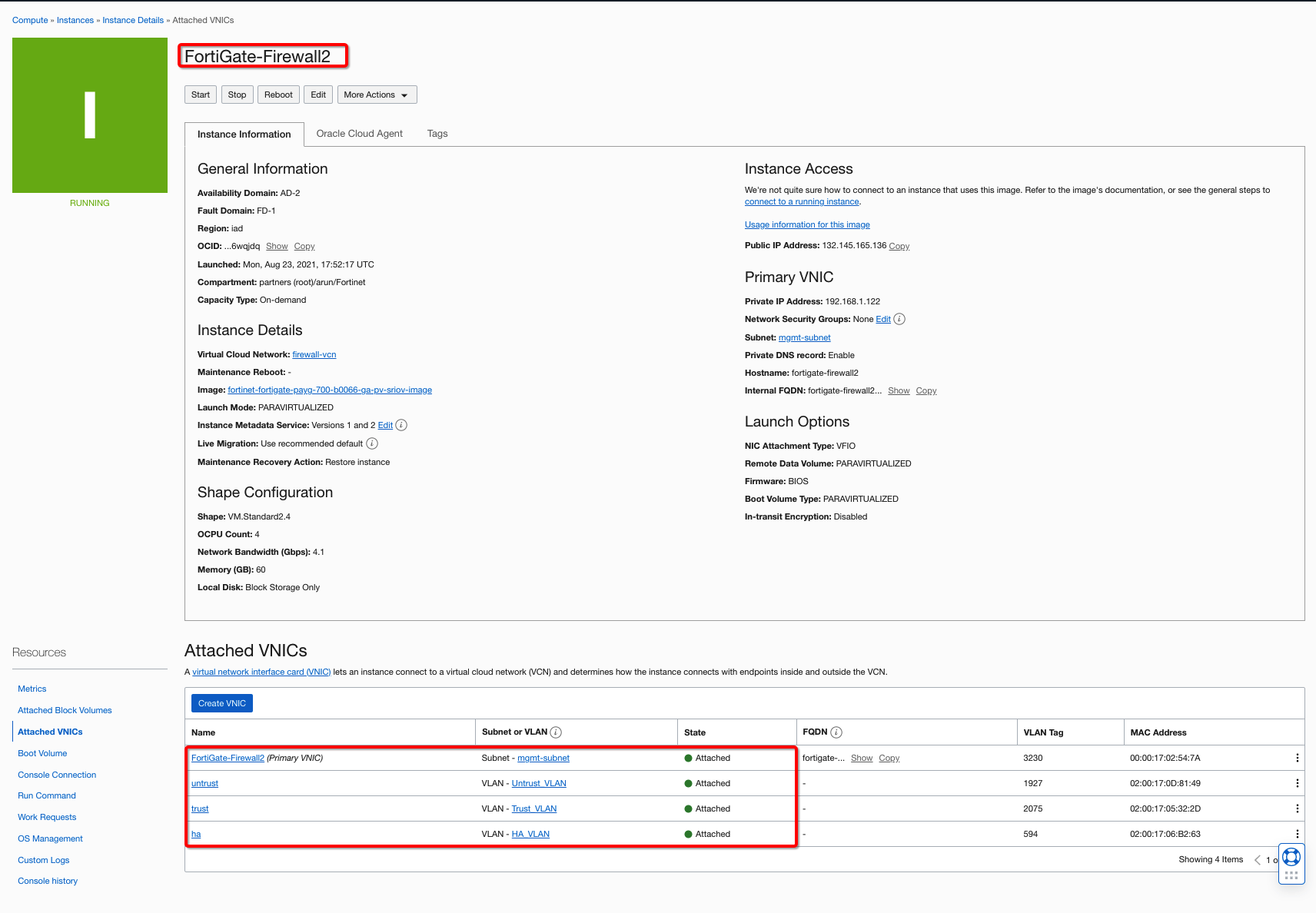
Figure 4: FortiGate primary firewall instance and vNICs
Firewall interfaces
To provide external connectivity, assign external access to the trust and untrust Layer 2 VLANs and utilize those private IP addresses to assign to firewall interfaces and use them in route tables.
The following example reflects how you can create Trust VLAN private IP address to associate firewall trust Interfaces and route targets to the VCN ingress route table. Assign external access to untrust and trust VLANs. The high availability VLAN typically doesn’t need external access because it’s created for sending control traffic. Assign the private IP addresses to firewalls and associate correct route tables to support the use case.
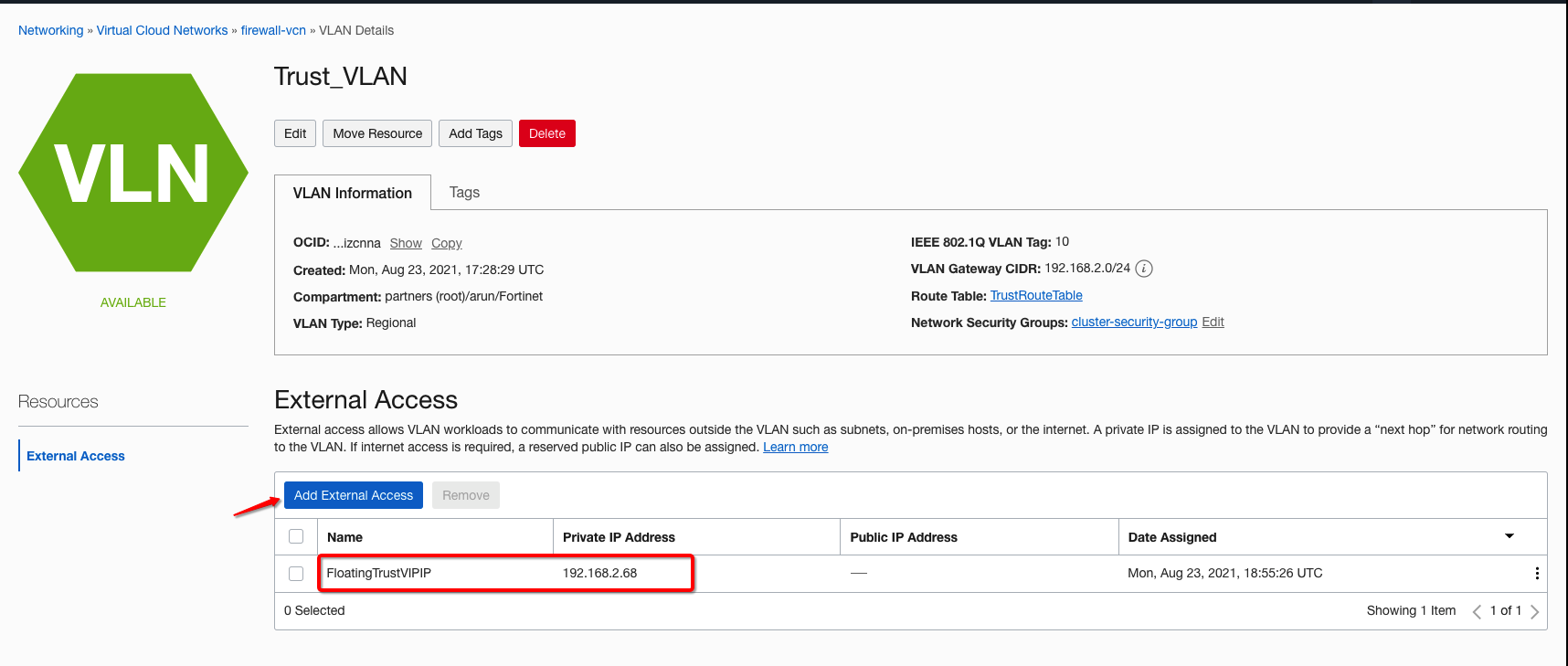
Figure 5: Trust VLAN external connectivity route target
Similarly, configure all firewall interfaces on each firewall, following the partner’s recommendation.
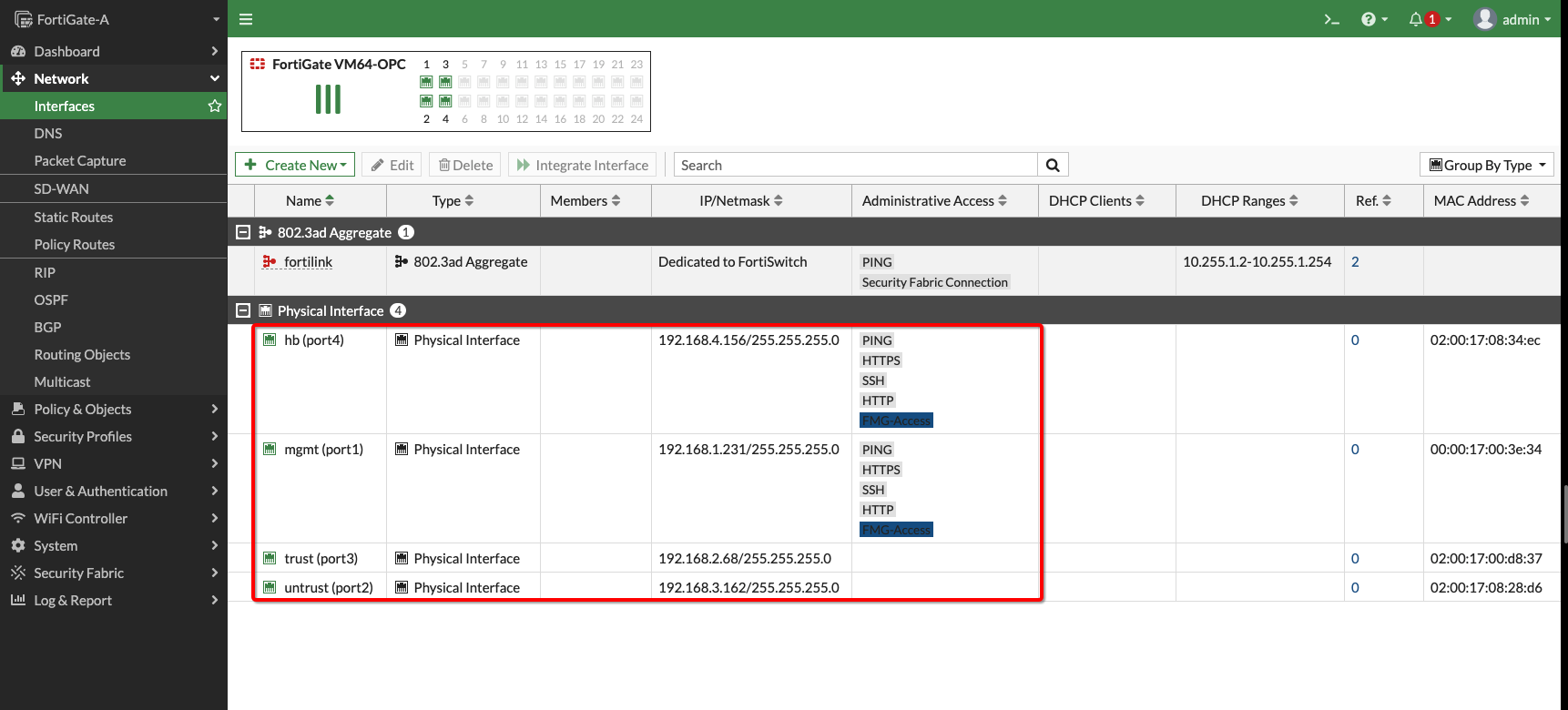
Figure 6: FortiGate primary firewall instance and vNICs
Security policies
Enable security policies to support VCN traffic. You can allow all for test purposes, but ensure that you enable only the required policies on FortiGate VMs in your production environment.
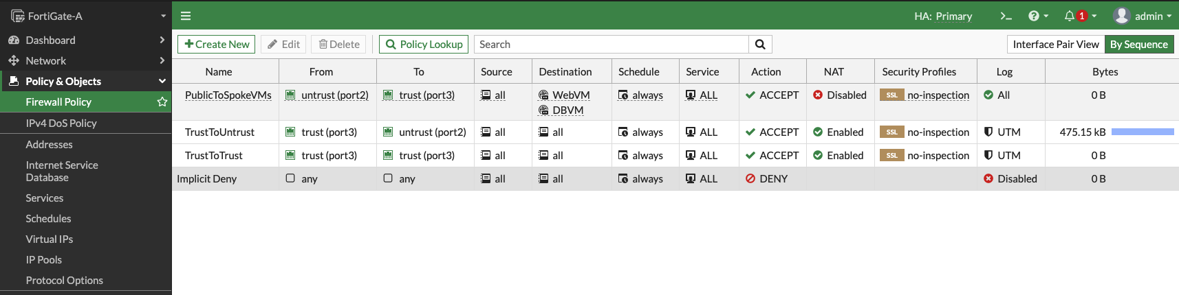
Figure 7: FortiGate firewall policies
Firewall routes
Ensure that the firewalls have correct routes for your spoke VCNs, Object Storage network, and default routes. For your reference, the following image shows the routing on the firewall:
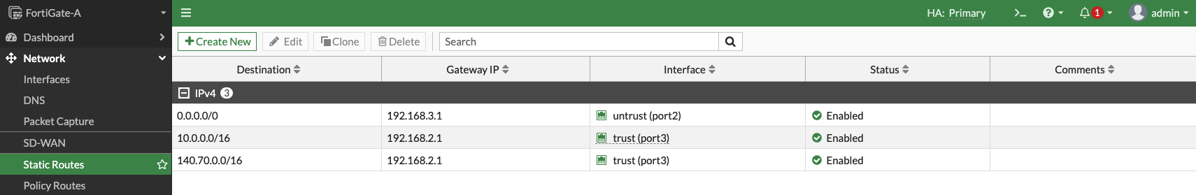
Figure 8: FortiGate firewall route rules
Firewall high availability cluster
Ensure the firewall’s high availability cluster is active and configuration is in sync.
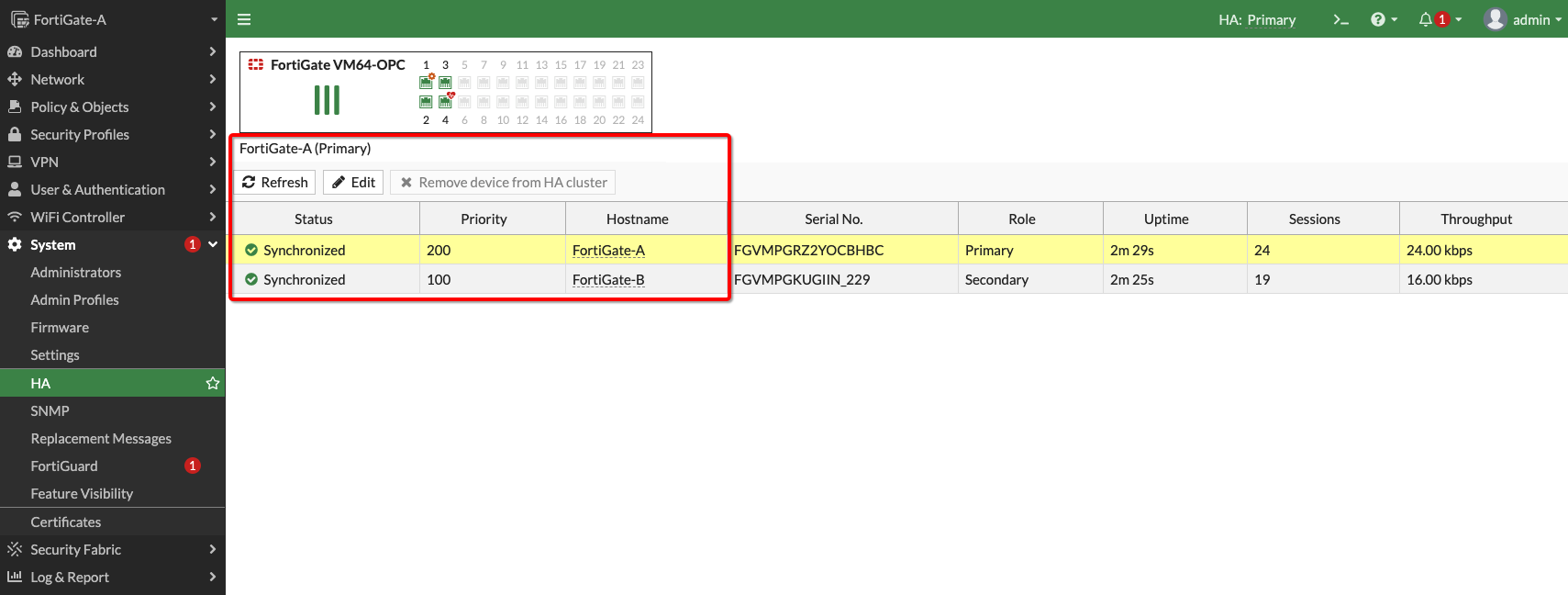
Figure 9: FortiGate firewall high availability configuration sync
Route tables on VCNs
Update the route tables to reflect the correct routes for the topology shared and update your topology with the following details:
- DRG route table: Entries for each spoke with the VCN CIDR as the destination and firewall trust VLAN floating IP as the target.
- Firewall untrust subnet: If you plan to have outbound connectivity, set an entry with default route as the destination and the internet gateway as the target.
- Firewall trust subnet: Create entries with each spoke VCN CIDR as the destination and the DRG as the target.
- Spoke VCN subnets route table: Set the default entry with each subnet as the destination and the DRG as the target.
Validation
At this point, you can validate the traffic from the client VMs and inspect the traffic from the FortiGate firewall. Initiate traffic from the client VM. For testing purposes, the user is trying to reach the web spoke VM from the database spoke VM, the reverse, and the internet.
Web to database spoke traffic and internet traffic
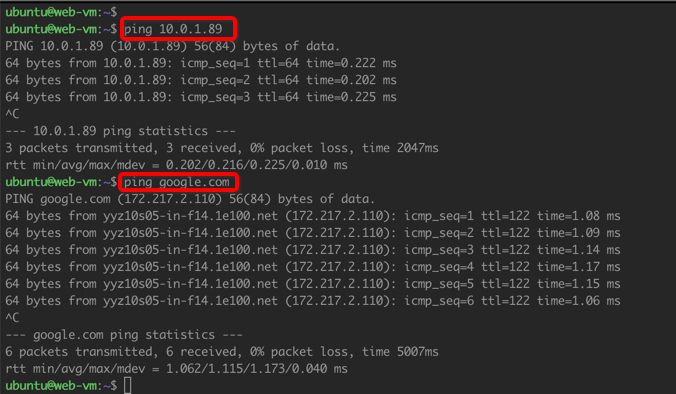
Figure 10: Web VM to database VM traffic and internet traffic
Database to web spoke traffic and internet traffic
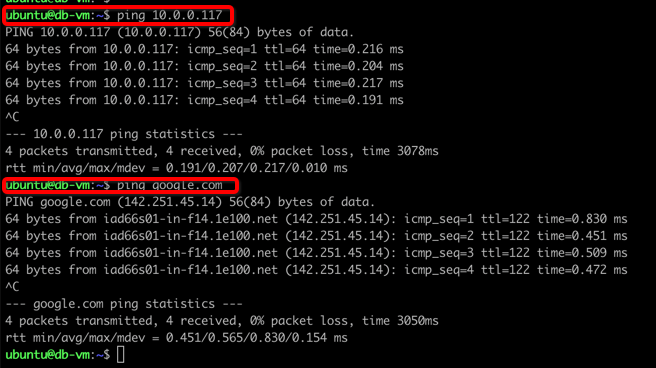
Figure 11: Database VM to web VM traffic and internet traffic
You can inspect the traffic flow from the FortiGate firewall. The web spoke VM has the IP address, 10.0.0.117, and the database spoke VM uses 10.0.1.89. The following image shows traffic between the spokes and to the internet:
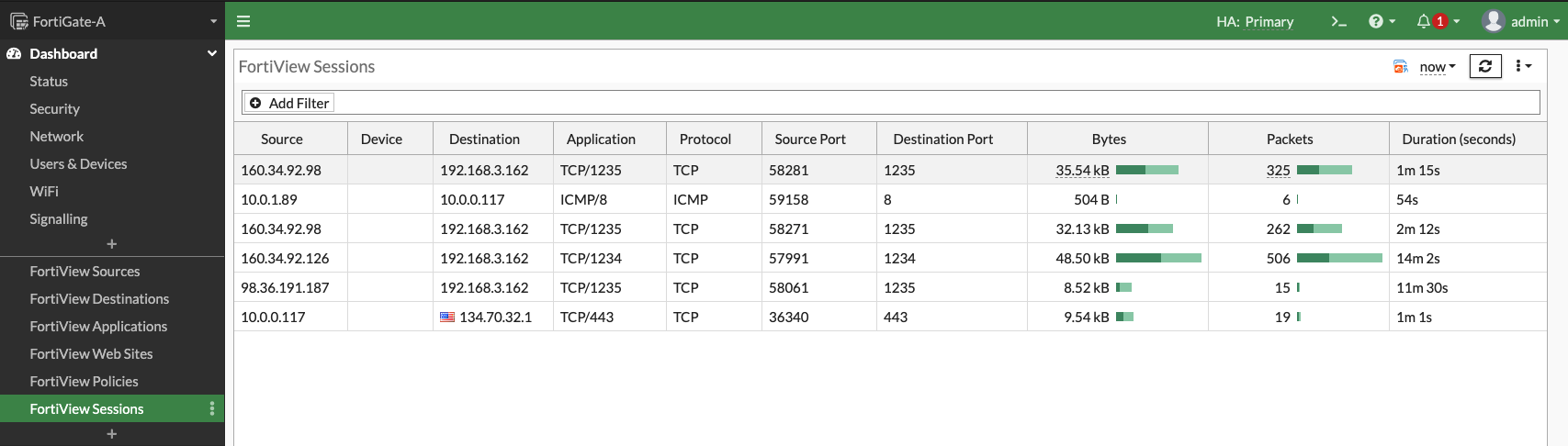
Figure 12: Traffic on the primary firewall VM
During high availability failover, the primary firewall becomes standby and the secondary firewall takes over the traffic.
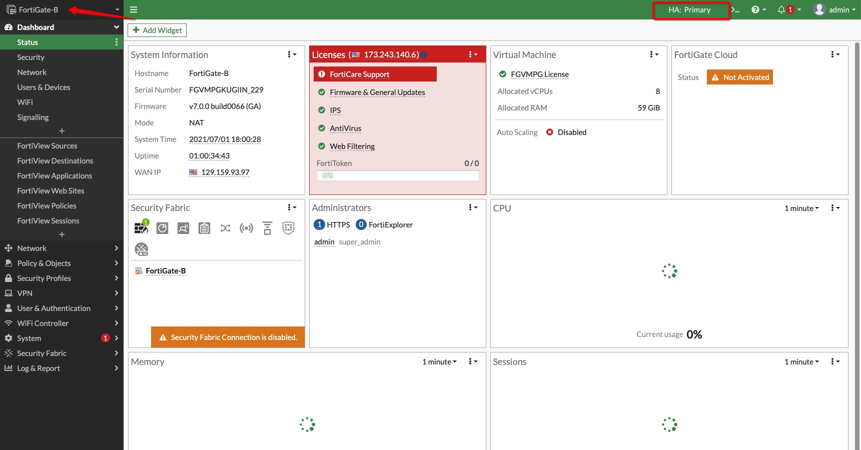
Figure 13: Secondary firewall as primary during failover
Conclusion
This post explained and showcased the OCI Layer 2 Networking feature with Fortinet’s FortiGate solution. We have covered a high availability use case that simplifies your firewall deployment on Oracle Cloud Infrastructure. Work with Oracle or your vendor team to allowlist your tenancy and validate your solution.
To learn more about Layer 2 Networking, see the following resources: