Oracle Cloud Infrastructure (OCI)’s flexible network Load Balancing service provides transparent pass-through load balancing of your Layer3/Layer4 (TCP/UCP/ICMP) workloads. This blog teaches you how you can use the flexible network load balancer in a sandwich topology with Check Point CloudGuard Network Security gateways to monitor and secure workloads traffic. We cover how to set up your flexible network load balancers and required configuration on the CloudGuard Network Security gateways.
Use case
We want to utilize flexible network load balancer to support on-premises or outside connectivity to OCI workloads using CloudGuard Network Security gateways to inspect and secure the traffic.
-
Set up connectivity from on-premises and internet networks to OCI: Follow the official documentation from on-premises options and Oracle Cloud Networking.
-
Deploy CloudGuard Network Security gateways from the provided topology. You can also refer to a different architecture to set up your environment.
-
Set up the provided configuration steps on OCI and CloudGuard Network Security gateways.
Current network load balancers require adding NAT rules on the CloudGuard Network Security gateways, but future features support NAT natively.
Prerequisites
-
An Oracle Cloud account. If you don’t have an account, you can sign up for an Oracle Cloud Free Tier account.
-
A working hub-and-spoke network topology with Check Point CloudGuard Network security gateways in your hub VCN. You can use CloudGuard bring-your-own-license or paid listings from OCI Marketplace. For this blog, we’ve validated R80.40 CloudGuard IaaS Gateway BOYL rev 1.2 version.
-
A working application load balancer-as-a-service to steer traffic to web application virtual machines (VMs)
- A working on-premises or internet inbound connection to your hub virtual cloud network (VCN)
Topology
You can refer the following topology to support this use case:
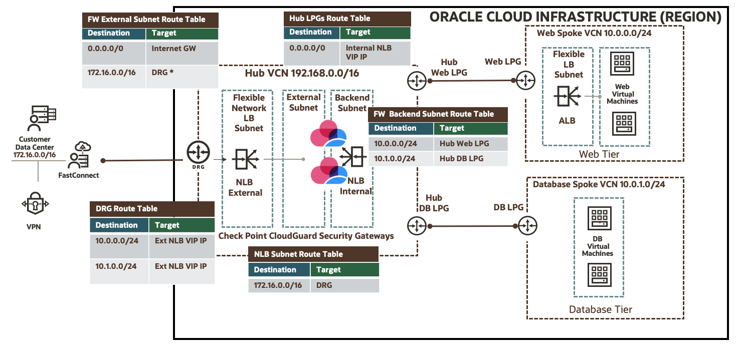
Figure 1: Use case network topology
You can follow this section to add the required minimum configuration on CloudGuard gateways and OCI to integrate the network load balancer sandwich topology. For more configurations, follow the official guide.
CloudGuard Network Security gateways
To support traffic, add the following minimum configuration features:
-
Open the required security policies
-
Create the required NAT policies
-
Add the correct route for spoke VCNs and default routes
CloudGuard Network Security gateways allow the end user to consume health checks on interfaces using HTTPS with 200 return code. You can create Allow All policies for test purposes and modify them as needed for your production environment. We use Check Point Security Management to support CloudGuard Network Security gateways.

Figure 2: Security policies
NAT policies
Enable NAT policies at a minimum to support traffic in the following directions:
-
North to south traffic: Create a source NAT to support traffic from either on-premises or the internet to your spoke VCNs so that the source NAT connects to the CloudGuard Network Security gateway’s frontend subnet IP addresses.
-
East to west traffic: Create NAT policies to support traffic within VCNs so that the source NAT connects to the CloudGuard Network Security gateway’s backend IP addresses.
-
Outbound traffic: Create NAT policies to support traffic from VCN virtual machines (VMs) to connect to the internet so that the source NAT connects to the CloudGuard Network Security gateway’s external interface IP addresses.

Figure 3: NAT policies
Routes
You need the correct routes for spoke VCNs and default addresses using gateway IP addresses. You can follow this diagram as a reference for each CloudGuard Network Security gateway.

Figure 4: Static routes
Oracle Cloud Infrastructure
With a working OCI setup, you need the following minimum prerequisites for this use case:
-
Create an external and internal network load balancer.
-
To support traffic, update route tables associated with subnets, local peering gateways, and dynamic routing gateways.
External network load balancer
-
Set visibility to Private with the listener as UDP/TCP/ICMP.
-
Ensure that your backend sets are associated with CloudGuard Network Security gateway external interface IP addresses.
-
Select HTTPS health check for backend sets.
Refer to the following diagrams for your configuration:

Figure 5: Create a network load balancer
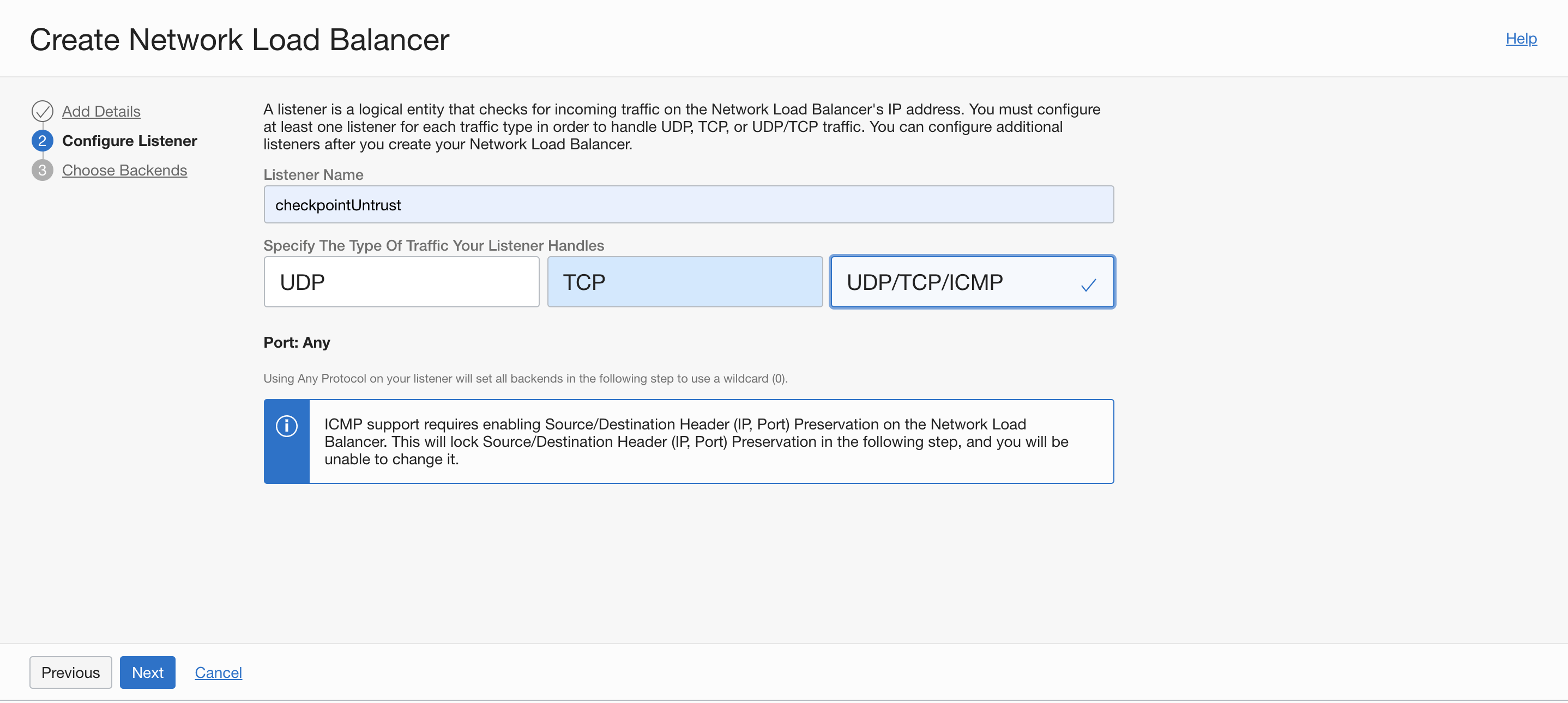
Figure 6: Create a network load balancer listener
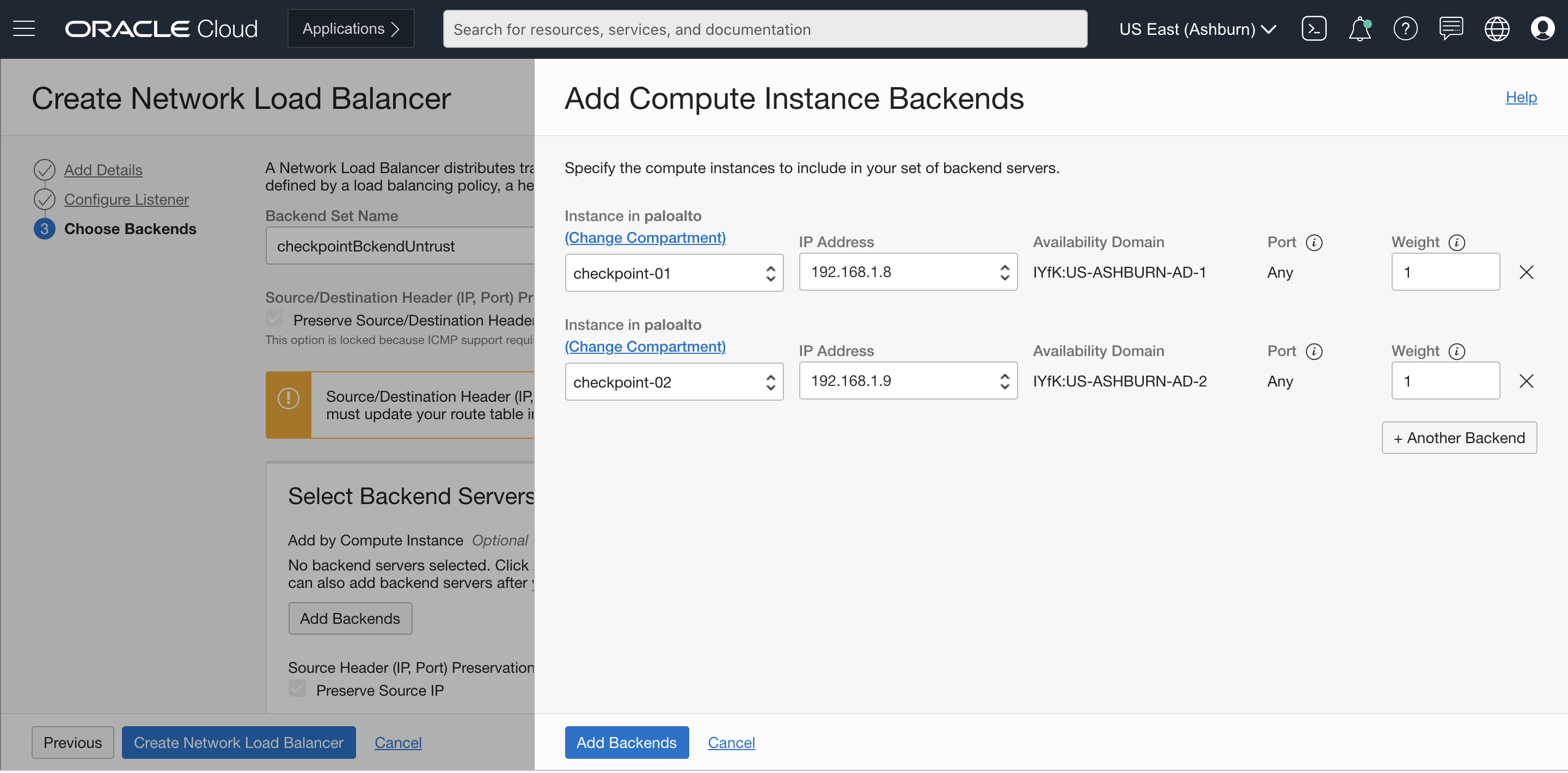
Figure 7: Add backends to load balancer
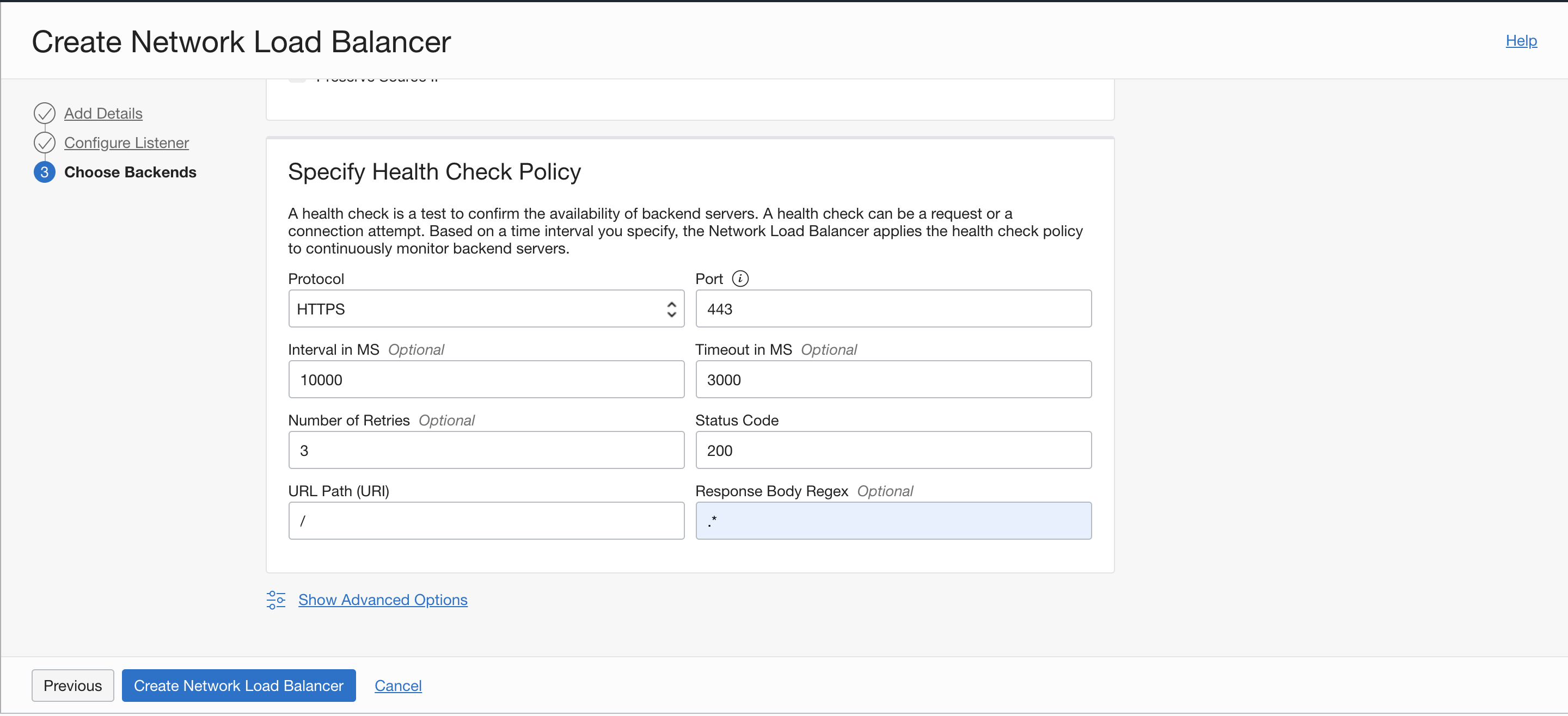
Figure 8: Add a backend health check policy to load balancer
Internal network load balancer
-
Set visibility to Private with the listener as UDP/TCP/ICMP in transparent mode.
-
Ensure that your backend sets are associated with CloudGuard Network Security gateway backend interfaces IP addresses.
-
Select HTTPS health check for backend sets
Refer to the following diagram for your configuration:

Figure 9: Check Point use case required flexible network load balancer health status
Route tables
Update route tables to reflect the correct routes from the shared topology with the following settings:
-
Dynamic routing gateway (DRG): Use each spoke VCN CIDR as the destination with the target as External Network Load Balancer VIP IP.
-
Network load balancer subnet: Use the on-premises CIDR as the destination with the target as DRG.
-
External subnet: Create an entry with the default route as the destination and internet gateway as the target. This configuration requires adding the public IP to the external interfaces of CloudGuard Security gateways
Create another entry with the on-premises or outbound CIDR as the destination and DRG as the target. This placeholder smooths the future transition to support NAT natively on the flexible network Load Balancing service. -
Backend subnet: Create entries with each spoke VCN CIDR as the destination with the target set as hub local peering gateways.
-
Local peering gateway (LPG) route tables: Create entries for each hub LPG as the destination with the target set as internal network load balancer VIP IP.
Validation
Now, you can validate the traffic from the source VM and verify the traffic from the Check Point Security Manager.
North-south traffic
Connect from the on-premises VM (172.16.1.69) to the destination application load balancer (10.0.0.138) over Port 80. The traffic gets the source NAT to backend interface IP address of CloudGuard Network Security gateways. The traffic responds through the web application VM, which has Apache application running on port 80.
[opc@nlbtestvm ~]$ hostname --all-ip-addresses
172.16.1.69
[opc@nlbtestvm ~]$ curl http://10.0.0.138
<h1>This is a Test Page Serving from Spoke VCN Web Application VM 1</h1>
[opc@nlbtestvm ~]$
Figure 10: On-premises to spoke VCN traffic
East-west and internet traffic
Connect from the database VM (10.0.1.2) to the destination application load balancer (10.0.0.138) over port 80. The traffic gets the source NAT to the backend interface IP addresses of CloudGuard Network Security gateways. Traffic responds through the web application VM, which has Apache application running on port 80. Traffic from the database spoke VM toward GitHub on the internet gets the source NAT to the external interface IP addresses of CloudGuard Network Security gateways.
[opc@db-app-2 ~]$ hostname --all-ip-addresses
10.0.1.2
[opc@db-app-2 ~]$ curl http://10.0.0.138
<h1>This is a Test Page Serving from Spoke VCN Web Application VM 1</h1>
[opc@db-app-2 ~]$ curl -I https://github.com | grep HTTP
  % Total    % Received % Xferd  Average Speed   Time    Time     Time  Current
                                 Dload  Upload   Total   Spent    Left  Speed
  0     0    0     0    0     0      0      0 --:--:-- --:--:-- --:--:--     0
HTTP/2 200
[opc@db-app-2 ~]$
Figure 11: Spoke VCN traffic
Conclusion
This post explained how to use a flexible network load balancer to support on-premises network traffic through Check Point CloudGuard Network Security gateways in a hub-and-spoke topology. You can use this post as a reference point to validate other use cases.
To learn more about how to use flexible network load balancers, load balancers, hub-and-spoke architecture, and more, see the following resources: