We are excited to announce the new capability to add the “OCI Load Balancer” as a member of the DR protection group in OCI Full Stack Disaster Recovery.
OCI Full Stack Disaster Recovery (Full Stack DR) provides a fully automated and comprehensive disaster recovery orchestration solution for all the layers of a full-stack cloud application, including infrastructure, database, and application. Using Full Stack DR, you can recover your full stack applications across OCI regions, or across availability domains within the same region.
Overview of OCI Load Balancer:
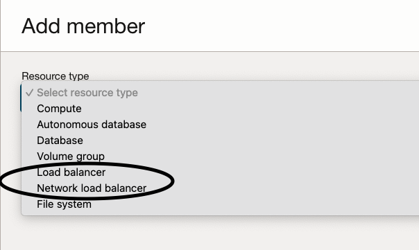
The OCI Load Balancer offers automated traffic distribution from a single access point to numerous servers accessible within your virtual cloud network (VCN). It is essential to note that there are two types of Load Balancers available.
Load Balancer – Provides layer 4 and layer 7 (TCP and HTTP) load balancing that routes network traffic with advanced flexible options. Load balancing improves resource utilization, facilitates scaling, and helps to ensure high availability. It’s important to note that the Load Balancer can be public or private.
Network Load Balancer – Provides non-proxy load balancing solution that performs pass-through load balancing of layer 3 and layer 4 (TCP/UDP/ICMP) workloads. Layer 4 load balancers forward network packets to and from the upstream server without inspecting the content of the packets. It’s important to note that the Network Load Balancer can be public or private.
Integration of Load Balancer with Full Stack DR
With the new capability to add the OCI Load Balancer as a member of a protection group, Full Stack DR offers built-in support for both the Load Balancer and Network Load Balancer for DR orchestration.
As pre-requisites, provision and configure Load Balancers in both the primary and standby (DR) regions. Below are the high-level steps to setup a Load Balancer.
- Create VCN and other related networking related resources
- Provision the load balancer or network load balancer with load balancer type ( public or private), IP address, and shape
- Configure backend sets, load balancing policy, and the health check policy
- Configure listeners, enable access and the error logs
- Configure load balancer subnet security rules to allow the intended traffic
- Optionally, associate listeners with SSL server certificate bundles to manage how the system handles SSL traffic.
For more information please refer to the OCI Load Balancer and Network Load Balancer documentation.
OCI Full Stack DR automatically generates built-in plan groups and steps for the load balancer backend set based on the type of DR plans (switchover, failover, start and stop drill) being configured. When adding Compute as a member type in the DR protection groups, you choose to add compute as a Moving instance or a Non-moving instance.Below are the high-level steps that need to be done in order to integrate an OCI Load Balancer for an existing DR protection group pair.
- Add load balancers as members in the primary and standby (DR) protection groups.
- Add dependent compute (moving and non-moving) instances as members in the primary and standby DR protection groups.
- Create the switchover, failover, start drill, and stop drill plans in the standby (DR) protection group.
- Full Stack DR will automatically generate plan groups depending on the plan type and plan member options that were selected
- During DR plan execution, in the case of moving instances, backend servers will be removed/added from the backend sets. In the case of non-moving instances, the backend server’s drain state/offline state will be set to true/false in the backend sets.
- Create separate backend sets for moving and non-moving instances options; you cannot mix and match moving and non-moving instances in the same backend set.
Let’s understand the concepts of the backend set and backend servers in the OCI Load Balancer.
Backend set– A backend set is a logical entity defined by a load balancing policy, a health check policy, and a list of backend servers.
Backend servers: Backend servers are the compute instances that are added in the backend set. The load balancer routes incoming traffic to these backend servers based on the policies that were specified for the backend set.
Full Stack DR will automatically generate the following plan groups and steps to update the backend sets for moving instances.
- Remove backends: Removes backend servers from the backend sets in the primary load balancer.
- Add backends: Adds backend servers to the backend sets in the standby load balancer.
Full Stack DR will automatically generate the following plan groups and steps to update the backend sets for non-moving instances.
- Drain state– Setting the server’s drain status to true, the primary load balancer stops forwarding new TCP connections and new non-sticky HTTP requests to this backend server. This setting allows an administrator to take the server out of rotation for maintenance purposes. Setting the server’s drain status to false, the standby load balancer allows the traffic.
- Offline state: Setting the server’s offline status to true, the primary load balancer forwards no ingress traffic to this backend server. Setting the server’s offline status to false, the standby load balancer forwards the traffic.
Here is the summary of the steps for the load balancer plan groups and steps for all the DR plan types.
For moving instances:
| DR Plan |
Primary |
Standby |
| Switchover |
Remove backends from the backend sets |
Add backends to the backend sets |
| Failover |
NA |
Add backends to the backend sets |
| Start Drill |
NA |
Add backends to the backend sets |
| Stop Drill |
NA |
Remove backends from the backend sets |
For non-moving instances:
| DR Plan |
Primary |
Standby |
| Switchover |
Drain and set the offline state of the backends in the backend sets to true |
Drain and set the offline state of the backends in the backend sets to false |
| Failover |
NA |
Drain and set the offline state of the backends in the backend sets to false |
| Start Drill |
NA |
Drain and set the offline state of the backends in the backend sets to false |
| Stop Drill |
NA |
Drain and set the offline state of the backends in the backend sets to true |
A step-by-step example
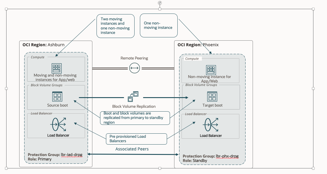
In this example, Ashburn (IAD) is the primary region, and Phoenix (PHX) is the DR region. We will use both moving and non-moving virtual machine topology.
We have provisioned and configured the below resources.
- Create two VM’s (instance-1 and instance-2) in the IAD region. These two VM’s are moving instances from IAD to PHX.
- Create VM (non-moving-iad) in the IAD region. This VM is non-moving instance.
- Create a volume group (vg-inst) with cross region replication ( from IAD to PHX) in the IAD region for the boot volumes of the virtual machines instance-1 and instance-2.
- Create load balancer (lbr-iad) in the IAD region with required configuration. Create backend set (iad-moving-bset), add the VM’s (instance-1 and instance-2) as backend servers. Create backend set ( iad-non-moving-bset), add the VM (non-moving-iad) as backend server.
- Create VM (non-moving-phx) in the PHX region. This VM is non-moving instance.
- Create load balancer (lbr-phx) in the PHX region with required configuration. Create backend set (phx-moving-bset) only. Create backend set ( phx-non-moving-bset), add the VM (non-moving-phx) as backend server.
For more information please refer the OCI Compute, Block Storage and OCI Load Balancer and Network Load Balancer documentation.
Let’s create DR plans for this DR topology.
1.Create & associate DR protection groups, add moving and non-moving compute and volume groups as members
- In the Ashburn (IAD) region, create a DR protection group as “lbr-iad-drpg”.
- In the Phoenix (PHX) region, create a DR protection group as “phx-iad-drpg”.
- Associate the “lbr-iad-drpg” DR protection group as the Primary role and the “lbr-phx-drpg” DR protection group as the Standby role.
- In the “lbr-iad-drpg” DR protection group, add the two compute instances (instance-1 and instance-2) as members with the moving-instance option.
- In the “lbr-iad-drpg” DR protection group, add the compute instance (non-moving-iad) as member with the non-moving instance option.
- In the “lbr-phx-drpg” DR protection group, add the compute instance (non-moving-phx) as member with the non-moving instance option.
For more information please refer OCI Full Stack DR documentation and Full Stack DR move VM tutorial.
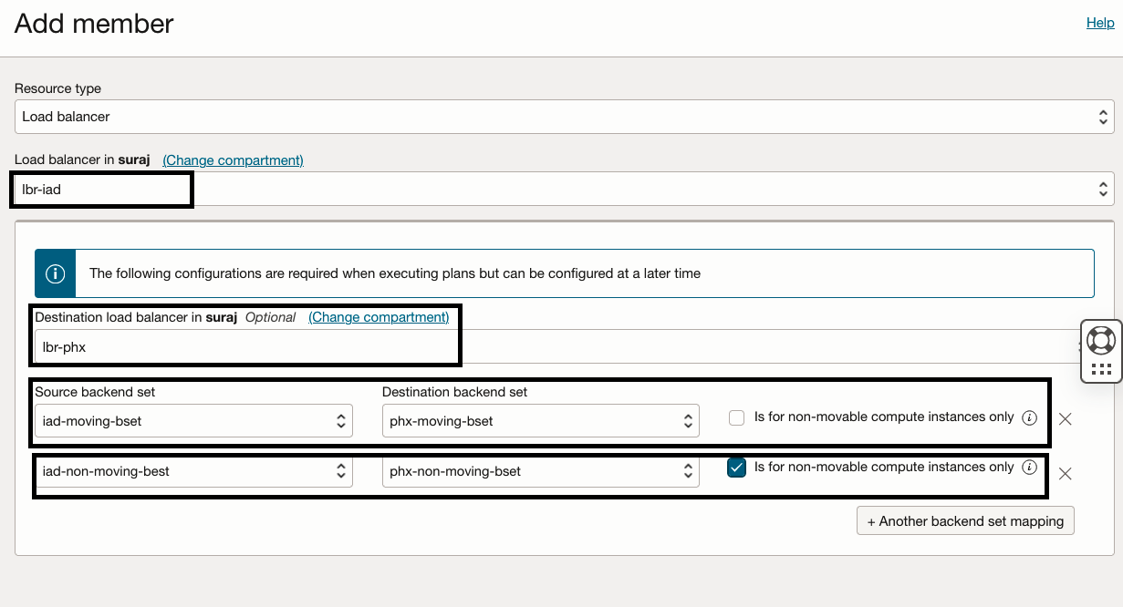
2.Add the Load balancer as members
- In the “lbr-iad-drpg” DR protection group, select resource type as the Load balancer and select “lbr-iad” as the member to add.
- Provide the source backend set and destination backend set mappings.
- Select source backend set as “iad-moving-bset” and destination backend set as “phx-moving-bset”.
- Click + to add another backend set mapping
- Select source backend set as “iad-non-moving-bset” and destination backend set as “phx-non-moving-bset”. Since this is for non-moving compute instance, you must select the check box “Is for non-movable-compute instance only”.
- Verify the inputs and click “Add”
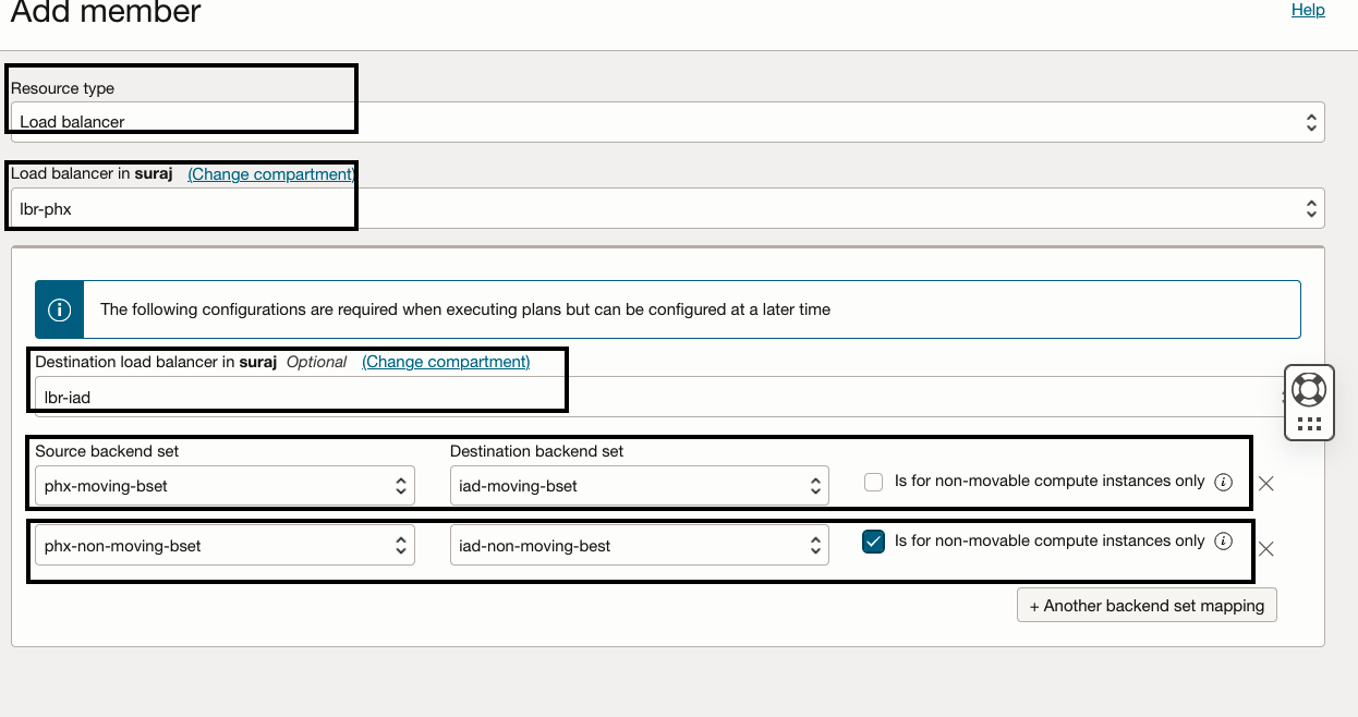
- In the “lbr-phx-drpg” DR protection group, select resource type as the Load balancer and select “lbr-phx” as the member to add.
- In the Destination load balancer, select the destination load balancer as “lbr-iad”.
- Provide the source backend set and destination backend set mappings.
- Select source backend set as “phx-moving-bset” and destination backend set as “iad-moving-bset”.
- Click + to add another backend set mapping
- Select source backend set as “phx-non-moving-bset” and destination backend set as “iad-non-moving-bset”. Since this is for non-moving compute instance, you must select the check box “Is for non-movable-compute instance only”.
- Verify the inputs and click “Add”
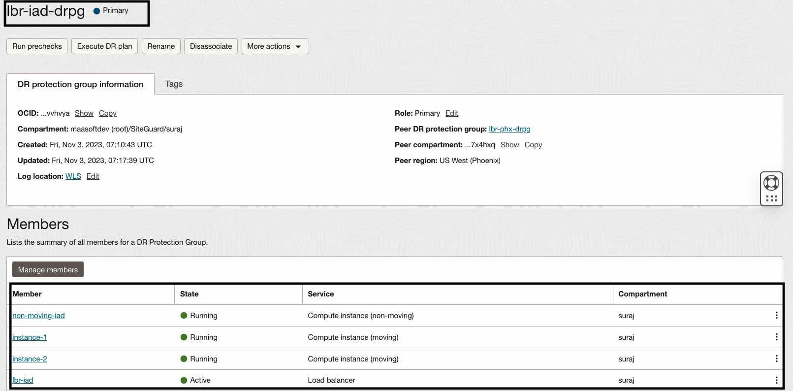
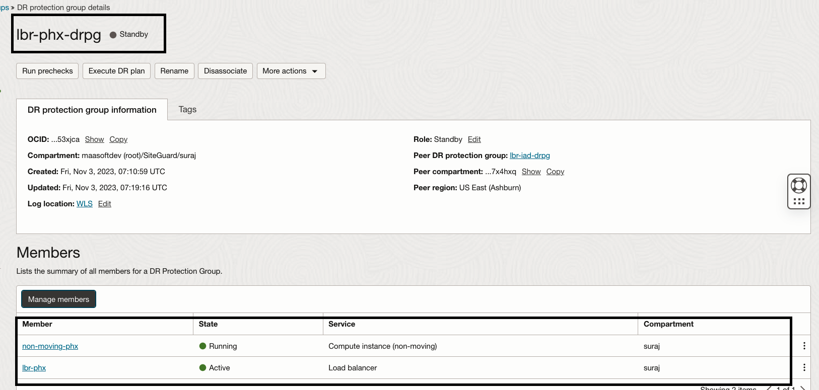
3.Verify the members in “lbr-iad-drpg” and “lbr-phx-drpg”
4. Steps for creating DR Plans
Navigate to DR Protection Group page in Phoenix region.
- In the “lbr-phx-drpg” DR protection group, click the Create Plan button.
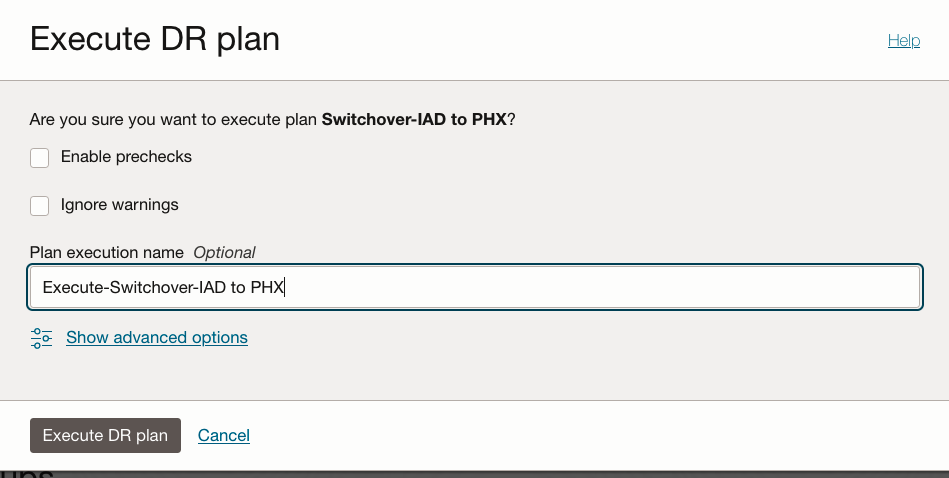
- Provide “Switchover-IAD to PHX” as the name of the plan.
- Select “Switchover” as the plan type.
- Click on “Create” to finish creating the Switchover plan.
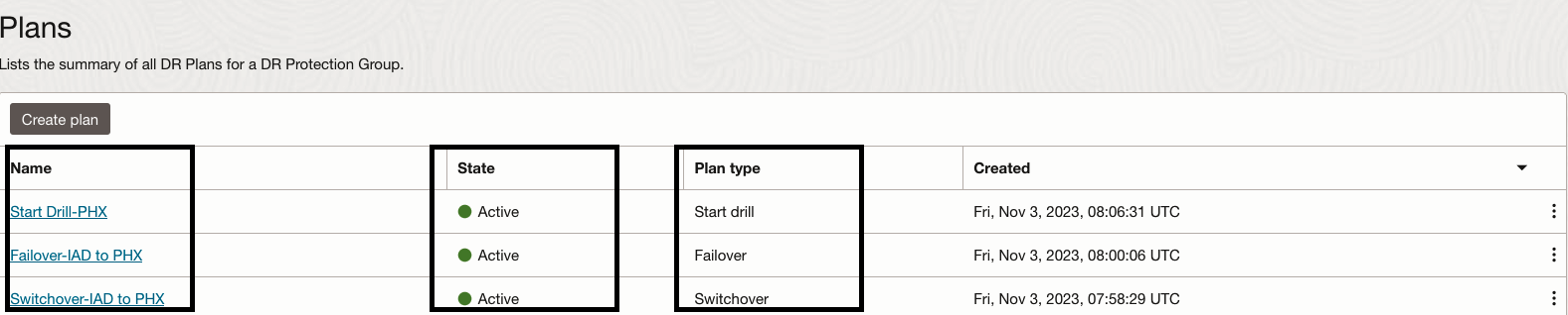
- Similarly, create Failover plan as “Failover-IAD to PHX” and start drill plan as “Start Drill-PHX”
- Full Stack DR will not allow to create Stop Drill plan unless “Start Drill-PHX” plan execution succeeds.
You should able to see all three plans as active.
5.Let’s explore the “Switchover-IAD to PHX” plan which we have created.
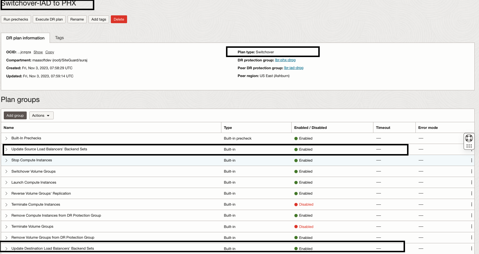
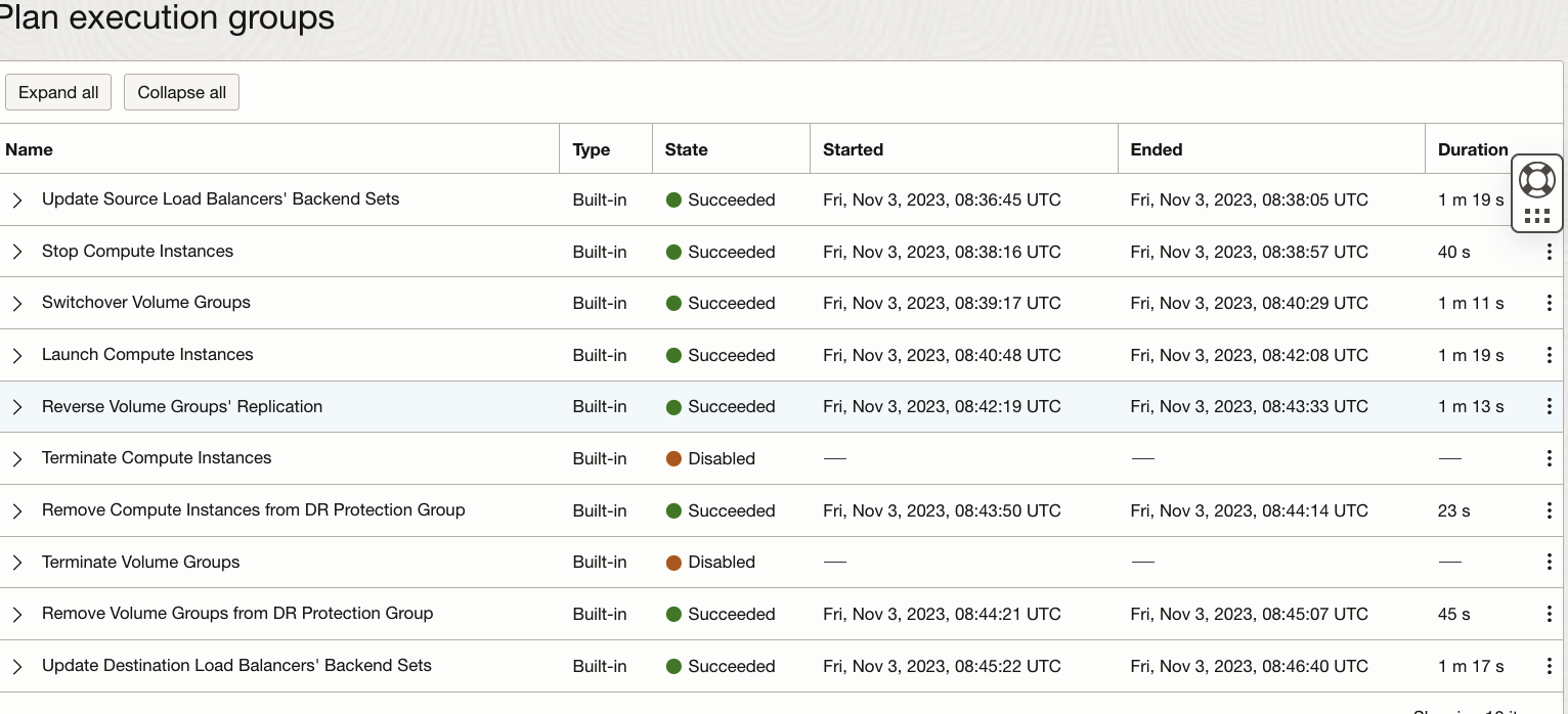
Full Stack DR has created multiple built-in plan groups based on the members we added to the DR protection groups. We are interested to see the Load balancer built-in plan groups. We have the option to customize the plan and add our own user-defined plan groups. However, in this example we will not be customizing this Switchover Drill plan.
- Update Source load Balancers’ Backend sets – Will remove backend servers (instance-1 an instance-2) from backend set “iad-moving-bset” and set the backend server(non-moving-iad) drain state and offline state to true in the backend set “iad-non-moving-bset”
- Update Target load Balancers’ Backend sets- Will add backend servers ( newly launched VMs) in the backend set “phx-moving-bset” and set the backend server (non-moving-phx) drain state and offline state to false in the backend set “iad-non-moving-bset”
6.Let’s run a precheck for the “Switchover-IAD to PHX” plan.
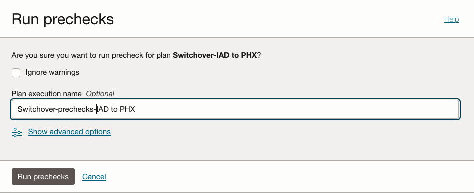
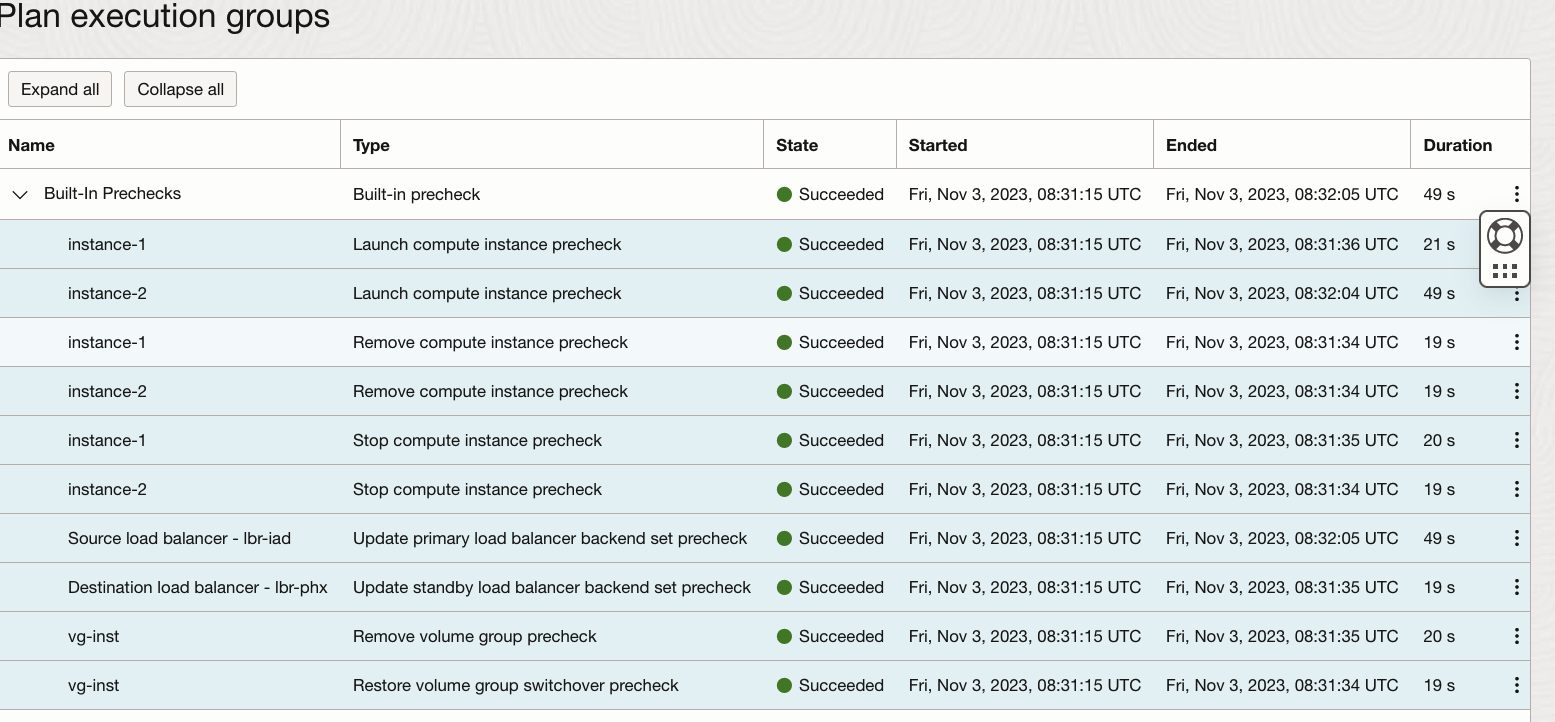
After a while, the “Switchover-IAD to PHX” prechecks plan execution succeeds.
7.Now let’s execute the “Switchover-IAD to PHX” plan and monitor the status.
After a while, the “Switchover-IAD to PHX” plan execution succeeds.
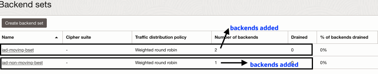
8.Verify the load balancer backend sets in IAD region. Backend servers are removed from “iad-moving-bset” and backend servers drain/offline status set to true in “iad-non-moving-bset”
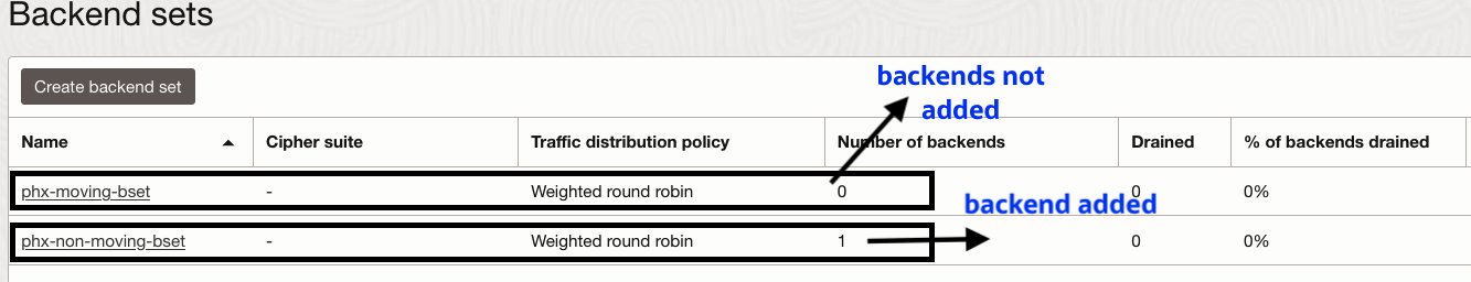
9.Verify the load balancer backend sets in PHX region. Backend servers are added to “phx-moving-bset” and backend servers drain/offline status set to false in “iad-non-moving-bset”
You can watch the demo of the Load Balancer using OCI Full Stack Disaster Recovery Support for OCI Load Balancer
Conclusion
Full Stack Disaster Recovery (DR) offers built-in support for both OCI Load Balancer and Network Load Balancer, simplifying the recovery process for these components in the context of a complete business application. This automation streamlines the recovery of the OCI Load Balancers in the event of a disaster or outage, ensuring the continued functionality and availability of the application.
Additional resources
Here are some additional resources to help you get started with Full Stack Disaster Recovery:
- Full Stack Disaster Recovery product page
- Full Stack Disaster Recovery User Guide
- Full Stack Disaster Recovery API Reference Guide
- Try out Full Stack Disaster Recovery using our hands-on lab
- OCI Load Balancer documentation
- OCI Network Load Balancer documentation
Feel free to connect with me directly on Twitter and LinkedIn