This blog covers aspects such as setting up network connectivity between the tenants and configuring secure ADW access. By following these guidelines, organizations can leverage the strengths of central OCI Dataflow processing in a tenancy, distributing processed data to ADW instances residing in different tenants in the same OCI region.
Components:
Use-cases discussion:
A central dataflow processing hub is an architectural approach designed to streamline and optimize data processing across multiple tenancies within Oracle Cloud Infrastructure (OCI). This model is especially beneficial for organizations managing complex, distributed environments that aim to centralize resource management, support multiple customer bases, and eventually implement disaster recovery (DR) solutions.
- Centralize data processing resource management for organizations spawning multiple tenancies – Organizations often operate multiple OCI tenancies to separate environments for security, compliance, or business unit differentiation. Centralizing data processing resources helps manage and optimize these dispersed assets efficiently.
- Processing hub for different customers, internal or external – A central processing hub can serve as a multi-tenant environment where data processing tasks for different customers (internal or external) are handled efficiently. This setup supports data isolation and ensures that customer data is processed securely.
- Active-active DR solution using different OCI regional availability domains (ADs) – An active-active disaster recovery (DR) solution involves writing data across multiple OCI regional ADs. This ensures high availability and resilience against regional outages or failures.
Network considerations:
When connecting Virtual Cloud Networks (VCNs) across different tenants in Oracle Cloud Infrastructure (OCI) using Local Peering Gateways (LPGs), several network considerations must be taken into account to ensure secure, efficient, and reliable communication. Local peering allows resources in different VCNs, which may belong to different OCI tenancies, to communicate with each other without using the public internet. Here are the key network considerations:
- IP Address Management – Ensure that the IP address ranges of the VCNs do not overlap.
- Network Security Groups (NSGs) – Properly configure security lists and NSGs to allow traffic between the peered VCNs. Ensure that the appropriate ports and protocols are permitted for the services that need to communicate.
- Local Peering Gateways (LPGs) are designed for low-latency connections within the same region, even considering
- Route Table Configuration – Configure the route tables for each VCN to direct traffic through the LPG, ensuring that routes are in place to handle traffic destined for IP ranges in the peered VCN.
- Compliance Requirements – Ensure that the peering setup complies with any regulatory and compliance requirements specific to your organization or industry. This could include data residency and data transfer regulations.
High-Level Network Diagram:
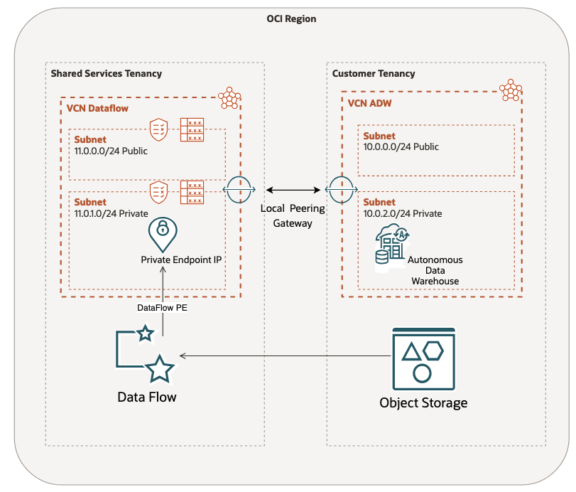
Figure 1 – The network diagram used in this example shows two pairing VCNs using Local Peering Gateways.
Data processing scheme:
In this example, the architecture depicted in Figure 2 enables seamless data integration, allowing dataflow applications to dynamically fetch, process, and store data for different tenants.
The primary benefits include scalability, cost efficiency, and leveraging a central set of OCI Dataflow pools.
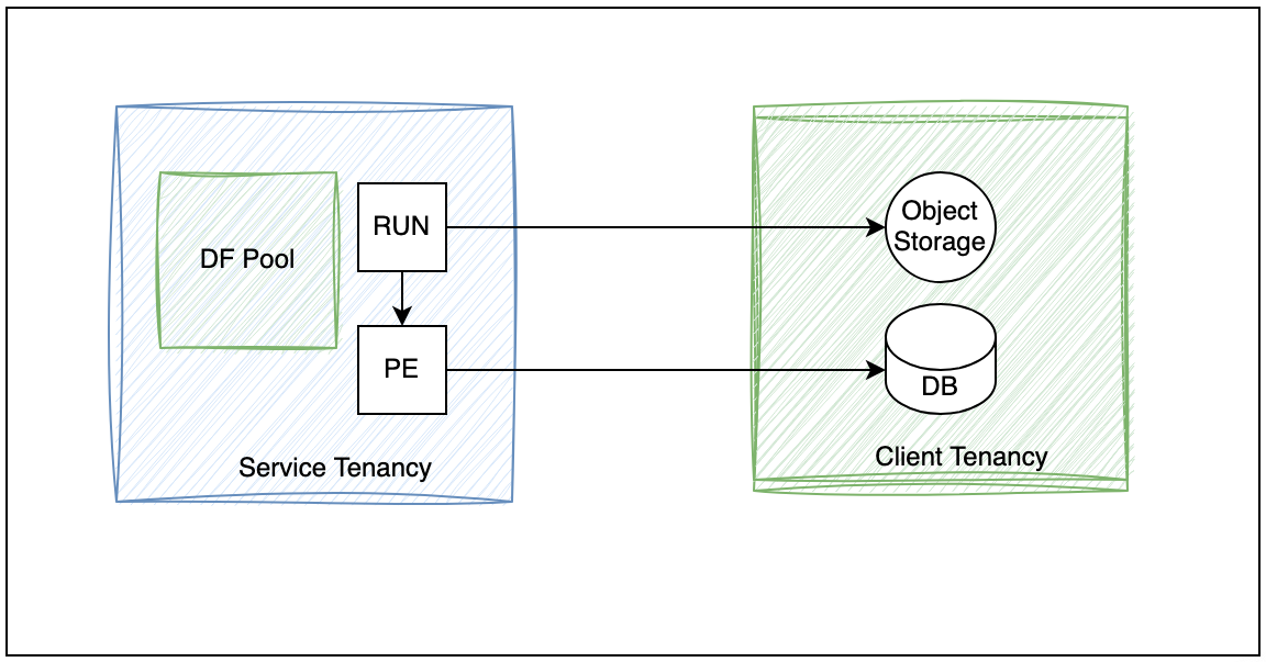
Figure 2 – Data Processing scheme
Implementation:
1- Object Store Cross tenancy policies
IAM policies necessary for cross-tenancy Object Store access must include permissions allowing specific resource or instance principals from one tenancy to read, write, and manage objects in another, ensuring secure and controlled access across the tenancies. For instance:
Client Tenancy
|
|
Service Tenancy
|
|
2- Local Peering Gateways
Setting up local peering gateways involves configuring the gateways in each tenancy to establish a connection that allows secure and efficient cross-tenancy access between the two tenancies’ Virtual Cloud Networks (VCNs). Figures 3 and 4 serve to demonstrate a common setting after the advertised OCID of one VCN is accepted by the other VCN.
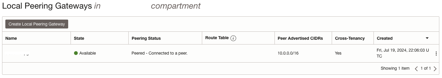
Figure 3 – Shared services VCN peered with customer tenancy VCN.
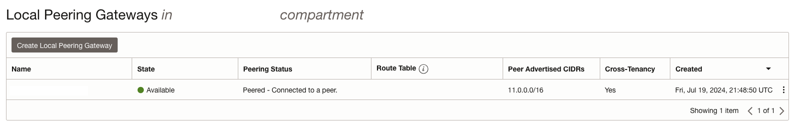
Figure 4 – Customer tenancy VCN resulting peered with service tenancy VCN.
3- ADW NSGs
Setting up Network Security Groups (NSGs) involves defining and applying specific security rules that allow and control the routing and traffic flow between two different Virtual Cloud Networks (VCNs), ensuring secure communication and data transfer. Figures 5 and 6 are examples of the routing allowed within the peered VCNs.
ADW NSG on the Client tenancy


Figure 5 – For customer tenancy, allow access to the ADW subnet on port 1522 and egress to the service tenancy VCN.
NSG on the Service tenancy

Figure 6 – Egress from the service tenancy to the customer VCN private subnet.
4- DNS Private Zone
Setting up a private DNS resolver and RRSet involves configuring a custom DNS service that resolves domain names within a private network and defining resource record sets (RRSets) to manage DNS records for internal routing and resolution. Figures 7 and 8 show the setup used in the service tenancy VCN to resolve the connectivity with the customer ADW instance. The full ADW FQDN can be retrieved by tnsnames.ora file present in the Wallet.zip file.
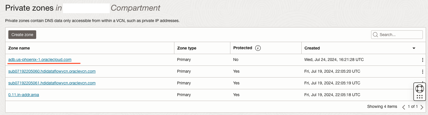
Figure 7 – DNS private zone for ADB instances in the service VCN.
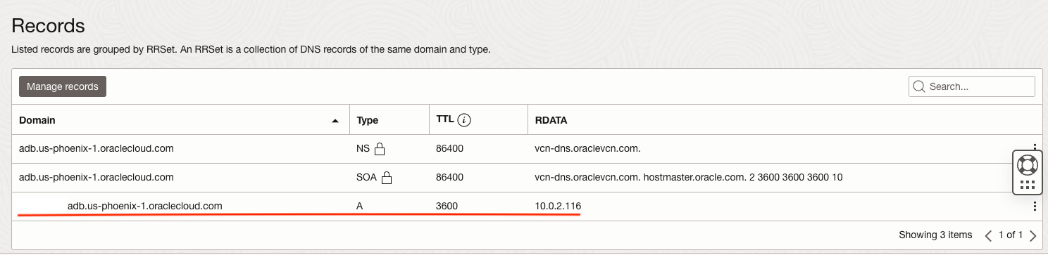
Figure 8 – ADW FQDN (the instance name is obfuscated in the figure) and its respective private IP address.
5- Create Dataflow PE – service tenancy
Setting up a Dataflow private endpoint in the service tenancy involves creating a secure connection that allows Dataflow applications to communicate within the customer tenancy private VCN where the ADW resides, ensuring data privacy and controlled access to resources. It also defines the DNS zones to resolve with the FQDN of the ADW instance (the instance name is hidden in Figure 9).
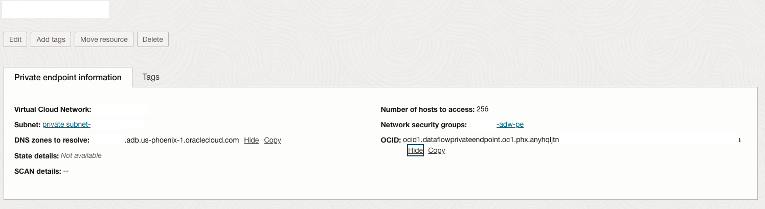
Figure 9 – Dataflow Private Endpoint.
6- Create a Dataflow application to test the connectivity
The application can created from the public GitHub repository, for instance, as shown in Figure 10. Once the application is launched to run, ensure it is attached to the private VCN of the service tenancy in this example.
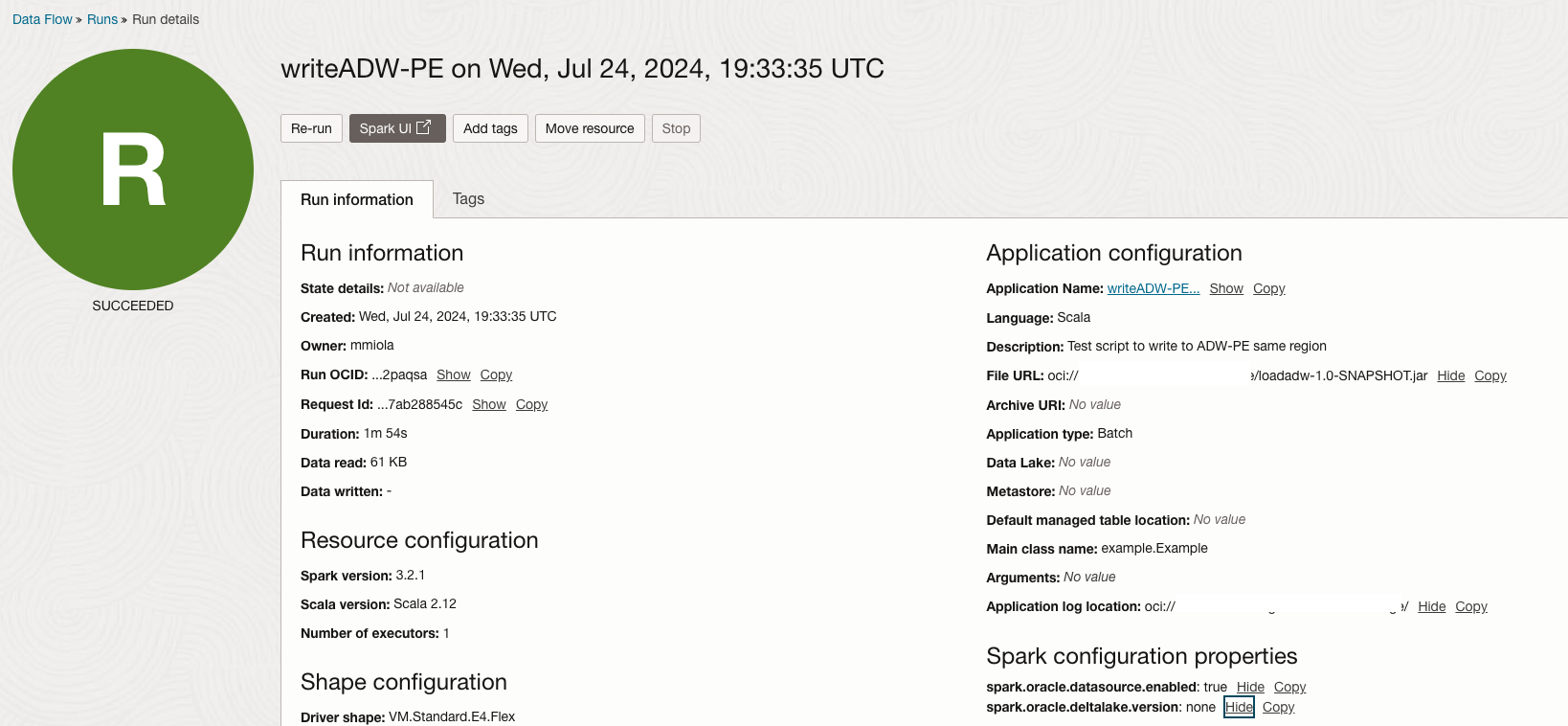
Figure 10 – Application to test ADW connectivity using the spark.oracle.datasource.enabled = true.
Other forms of testing connectivity exist, such as the Network Path Analyzer, which provides a unified and intuitive capability for identifying virtual network configuration issues that impact connectivity.
Limitations of the approach:
Using local peering gateways to enable connectivity from service tenancy to customer tenancies has several limitations.
Firstly, the scope of the peering is restricted to Virtual Cloud Networks (VCNs) within the same region, limiting cross-region connectivity.
The tenancy limit for the local peering gateway is 10 by default, and the route tables are 300, which can be increased by service requests.
Additionally, local peering does not support transitive routing, meaning traffic cannot automatically route through multiple VCNs. Security policies must be meticulously managed to ensure that only authorized traffic flows between the tenancies, which can increase the complexity of network configurations.
Conclusions:
This architecture enables seamless data integration, allowing dataflow applications to dynamically fetch, process, and store data for different tenants. The primary benefits include scalability, cost efficiency, and leveraging a central set of dataflow pools.
Implementing a central dataflow processing hub within OCI provides significant resource management, customer processing, and disaster recovery advantages. By leveraging OCI’s capabilities, organizations can achieve a scalable, secure, and resilient data processing environment. This approach optimizes resource utilization and cost and enhances the ability to serve multiple customers efficiently while ensuring robust DR capabilities across regions.
References:
https://docs.oracle.com/en-us/iaas/Content/Network/Tasks/LPG_management.htm
https://docs.oracle.com/en-us/iaas/Content/Network/Tasks/localVCNpeering.htm
https://docs.oracle.com/en-us/iaas/data-flow/using/pe-allowing.htm
https://docs.oracle.com/en-us/iaas/Content/Network/Tasks/resolver-add-view.htm#top