Overview:
In this document, we will be taking a look at the fundamentals of VirtIO from a technical standpoint as well as a deep dive into some of its key areas. This introduction to VirtIO is written assuming the reader has little to no working knowledge of VirtIO, but should also be a helpful refresher to those who are already familiar.
We’ll start with going over what VirtIO actually is and why we use it. Then we’ll get more technical and provide further detail about key areas of VirtIO, i.e. VirtIO devices & drivers, VirtQueues, and VRings (or “areas”). Lastly, to bring it all full circle, we’ll look at a working example of a VirtIO device’s VirtQueue in Qemu (with some code) and see how everything fits together in the VirtIO world.
What is VirtIO?
Formally, VirtIO, or virtual input & output, is an abstraction layer over a host’s devices for virtual machines. But what does that even mean? Essentially, it’s an interface that allows a virtual machine to use its host’s devices via minimized virtual devices called VirtIO devices. These VirtIO devices are minimal because they’re implemented with only the bare necessities to be able to send and receive data. This is because, with VirtIO, we let the host handle the majority of the setup, maintenance, and processing on its actual physical hardware devices. A VirtIO device’s role is more or less getting data to and from the host’s actual physical hardware.
For example, let’s say we have a VM (virtual machine) running on a host and the VM wants to access the internet. The VM doesn’t have its own NIC to access the internet, but the host does. For the VM to access the host’s NIC, and therefore access the internet, a VirtIO device called virtio-net can be created. In a nutshell, it’s main purpose is to send and receive network data to and from the host. In other words, let virtio-net be a liaison for network data between the host and the guest.
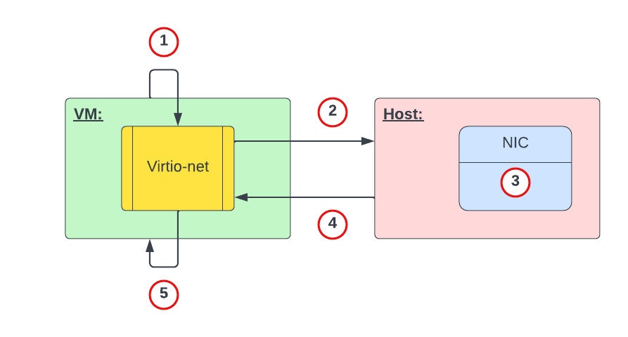
Figure 1 above represents, at a high level, the process of a VM requesting and receiving network data from the host. The high level interaction would be something like the following:
- VM: I want to go to google.com. Hey virtio-net, can you tell the host to retrieve this webpage for me?
- Virtio-net: Ok. Hey host, can you pull up this webpage for us?
- Host: Ok. I’m grabbing the webpage data now.
- Host: Here’s the requested webpage data.
- Virtio-net: Thanks. Hey VM, here’s that webpage you requested.
Although this is an oversimplified example, the core idea remains intact. That is, make the host’s hardware do as much of the work as possible and let VirtIO handle sending and receiving data. Offloading the bulk of the work to the host makes execution on the VM faster and more efficient as compared to if it were emulating a device, for example.
Another important aspect of VirtIO is that its core framework is standardized to an official VirtIO specification. The VirtIO spec defines standard requirements that VirtIO devices and drivers must meet (e.g. feature bits, statuses, configuration, general operations, etc.). This is important as this means that, regardless of the environment or operating system using VirtIO, the core framework of its implementation must be the same.
While there is conformance for VirtIO implementations, there’s also some leeway in how things are organized and set up. For example, the virtqueue structure in the Linux kernel is organized differently compared to Qemu’s VirtQueue structure. However, once you understand one implementation of VirtIO (e.g. in Qemu) it’s much easier to understand other implementations.
Why (or why not) VirtIO?
In the example above, we used the host’s network device for our VM to access the internet, but what about emulating a network device for our VM instead? With emulation we can imitate any device, even one that wouldn’t have been physically supported on our host’s hardware. So, why bother limiting ourselves to the host’s devices and capabilities if we can just emulate any device for our VM? To answer this, let’s first understand the difference between virtualization and emulation.
Virtualization vs. Emulation:
In emulation, software fills in for hardware and acts as if it were real hardware. Recall that in our previous example our VM used a virtio-net device to communicate with the host’s NIC. What if we wanted our VM to use a NIC that our host didn’t have and doesn’t support, i.e. some legacy device. In this case, we can use emulation and get software to fill in for the missing hardware support. We can also use emulation to have our VM run on a completely different operating system meant for other hardware (e.g. MacOS on a Windows PC).
Emulation is preferred when you need to use a device or software that your host’s hardware doesn’t have or doesn’t support. However, emulation doesn’t come without costs as the software filling in for the missing hardware is extra code that the host’s CPU will have to process. Having dedicated hardware will always be faster!
In virtualization, software splits the host’s physical hardware for guest VMs to use. This splitting of the host’s hardware to each guest VM essentially “dedicates” that portion of hardware to that VM, making that VM think it has its own hardware (when really it’s just “borrowing” it from the host). The key idea for virtualization here is that each guest has dedicated direct access to that portion of the host’s hardware. Note that “dedicated” here does not mean that the host would be deprived of said device. It’s more like sharing rather than giving total ownership of specific hardware.
Of course, since virtualization splits up the host’s resources, naturally, our guests are limited to what the host’s hardware supports. With regards to VirtIO devices, this is it’s input / output (NIC, block, memory, etc.) virtualization. In other words, it’s the communication framework between the host and guest for I/O devices.
Why (or why not) VirtIO? (Cont.)
It’s clear that both virtualization and emulation are techniques that imitate hardware via software. However, these techniques are used to meet a different set of expectations. In short, you would choose emulation over virtualization if you need to:
- Run an OS meant for different hardware (e.g. MacOS on PC, console-based games on PC, etc.)
- Run software meant for another OS (e.g. Microsoft Word on MacOS)
- Run legacy devices on unsupported hardware
Comparatively, you would choose virtualization over emulation if you:
- Care about host and guest performance (dedicated hardware)
- Don’t need support for legacy software or hardware
- Need to run multiple guest instances with efficient utilization of the host’s resources
VirtIO Architecture
The architecture of VirtIO has three key parts: front-end drivers, back-end devices, and its VirtQueues & VRings. In the diagram below, we can see where each part is in a typical host and guest setup with VirtIO (e.g. no VHost, SR-IOV, etc.).
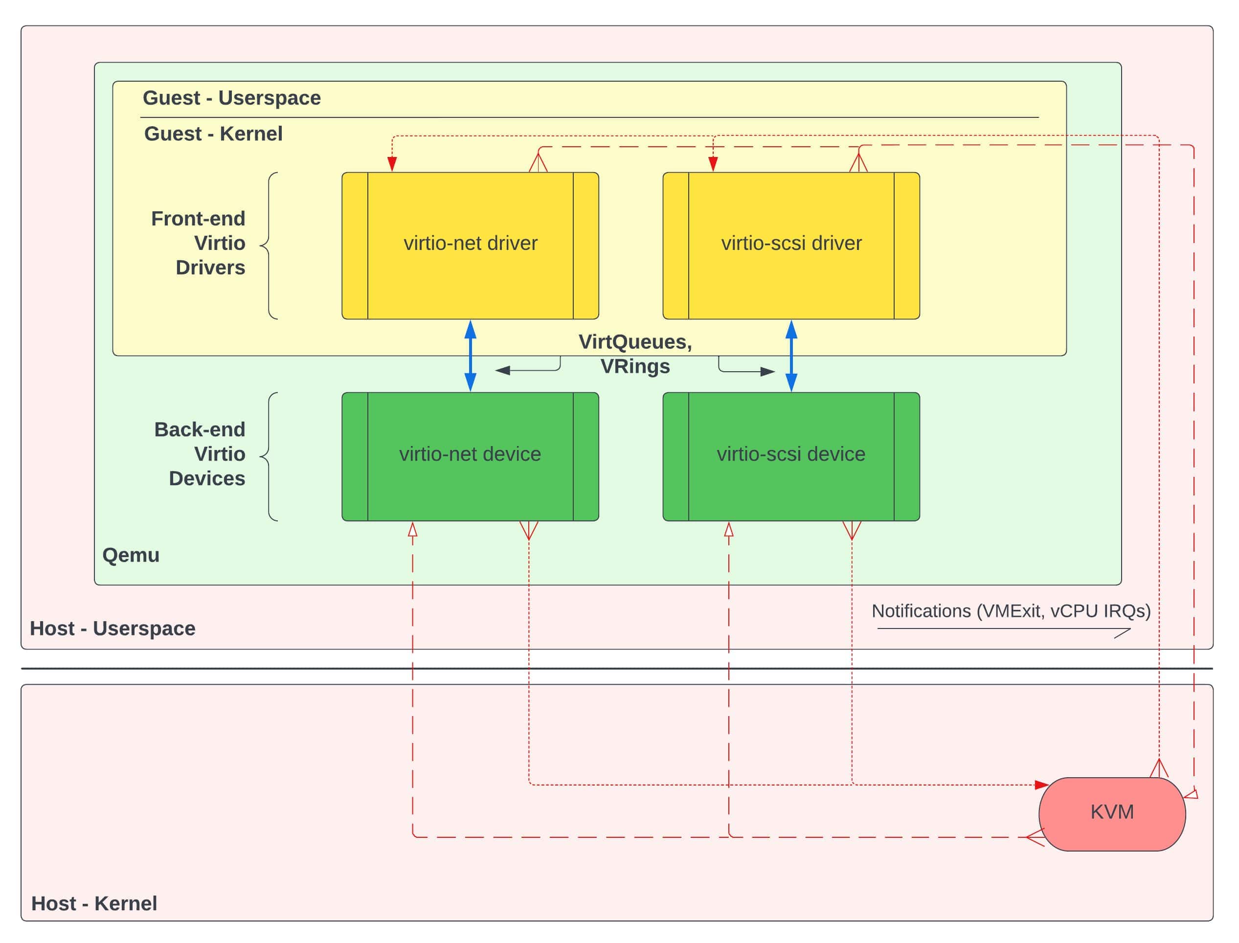
In figure 2 we can see that the front-end VirtIO drivers exist in the guest’s kernel, back-end VirtIO devices exist in the hypervisor (Qemu), and communication between them is handled in the data plane via VirtQueues & VRings. We can also see notifications (e.g. VMExits, vCPU IRQs) from VirtIO drivers and devices which are routed to KVM interruptions. We won’t go into detail about these notifications in this document, but it’s sufficient for now to know they exist.
VirtIO Drivers (Front-End):
In a typical host and guest setup with VirtIO, VirtIO drivers exist in the guest’s kernel. In the guest’s OS, each VirtIO driver is considered a kernel module. A VirtIO driver’s core responsibilities are:
- accept I/O requests from user processes
- transfer those I/O requests to the corresponding back-end VirtIO device
- retrieve completed requests from its VirtIO device counterpart
For example, an I/O request from virtio-scsi might be a user wanting to retrieve a document from storage. The virtio-scsi driver accepts the request to retrieve said document and sends the request to the virtio-scsi device (back-end). Once the VirtIO device has completed the request, the document is then made available to the VirtIO driver. The VirtIO driver retrieves the document and makes it available to the user.
VirtIO Devices (Back-End):
Also in a typical host and guest setup with VirtIO, VirtIO devices exist in the hypervisor. In figure 2 above and for this document, we’ll be using Qemu as our (type 2) hypervisor. This means that our VirtIO devices will exist inside the Qemu process. A VirtIO device’s core responsibilities are:
- accept I/O requests from the corresponding front-end VirtIO driver
- handle the request by offloading the I/O operations to the host’s physical hardware
- make the processed requested data available to the VirtIO driver
Returning to the virtio-scsi example; the virtio-scsi driver notifies its device counterpart, letting the device know that it needs to go and retrieve the requested document in storage on actual physical hardware. The virtio-scsi device accepts this request and performs the necessary calls to retrieve the data from the physical hardware. Lastly, the device makes the data available to the driver by putting the retrieved data onto its shared VirtQueue.
VirtQueues:
The last key part to the VirtIO architecture is VirtQueues, which are data structures that essentially assist devices and drivers in performing various VRing operations. VirtQueues are shared in guest physical memory, meaning that each VirtIO driver & device pair access the same page in RAM. In other words, a driver and device’s VirtQueues are not two different regions that are synchronized.
There is a lot of inconsistency online when it comes to the description of a VirtQueue. Some use it synonymously with VRings (or virtio-rings) whereas others describe them separately. This is due to the fact that VRings are the main feature of VirtQueues, as VRings are the actual data structures that facilitate the transfer of data between a VirtIO device and driver. We’ll describe them separately here since there’s a bit more to a VirtQueue than just its VRings alone.
Figure 3 below shows Qemu’s version of the VirtQueue and VRing data structures.
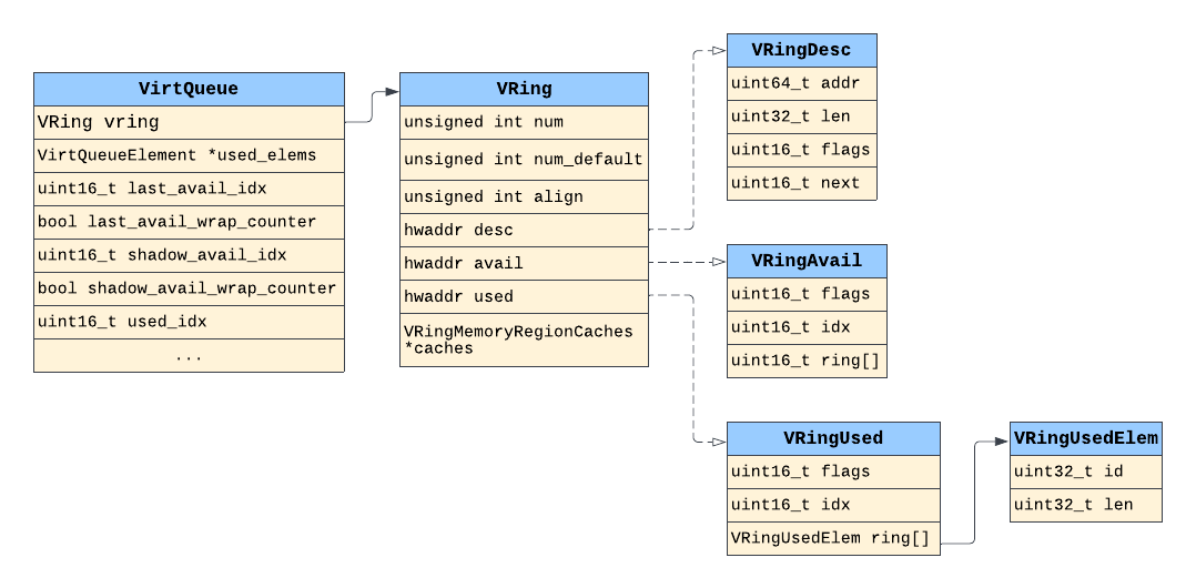
In Qemu’s VirtIO framework, we can clearly see the difference and relationship between a VirtQueue data structure and its VRing’s data structures (e.g. VRing, VRingDesc, VRingAvail, VRingUsed).
Other than the VRings themselves, a VirtQueue also facilitates the use of various flags, indices, and handlers (or callback functions), all of which are used for VRing operations in one way or another. One caveat to this, though, is that a VirtQueue’s organization is specific to the guest’s OS and whether we’re talking about userspace (e.g. Qemu) or kernel VirtIO framework. Also, the operations of VirtQueues are specific to the VirtIO configuration (e.g. split vs. packed VirtQueues).
For example, figure 4 below shows the Linux kernel’s version of its VirtQueue and VRing data structures.
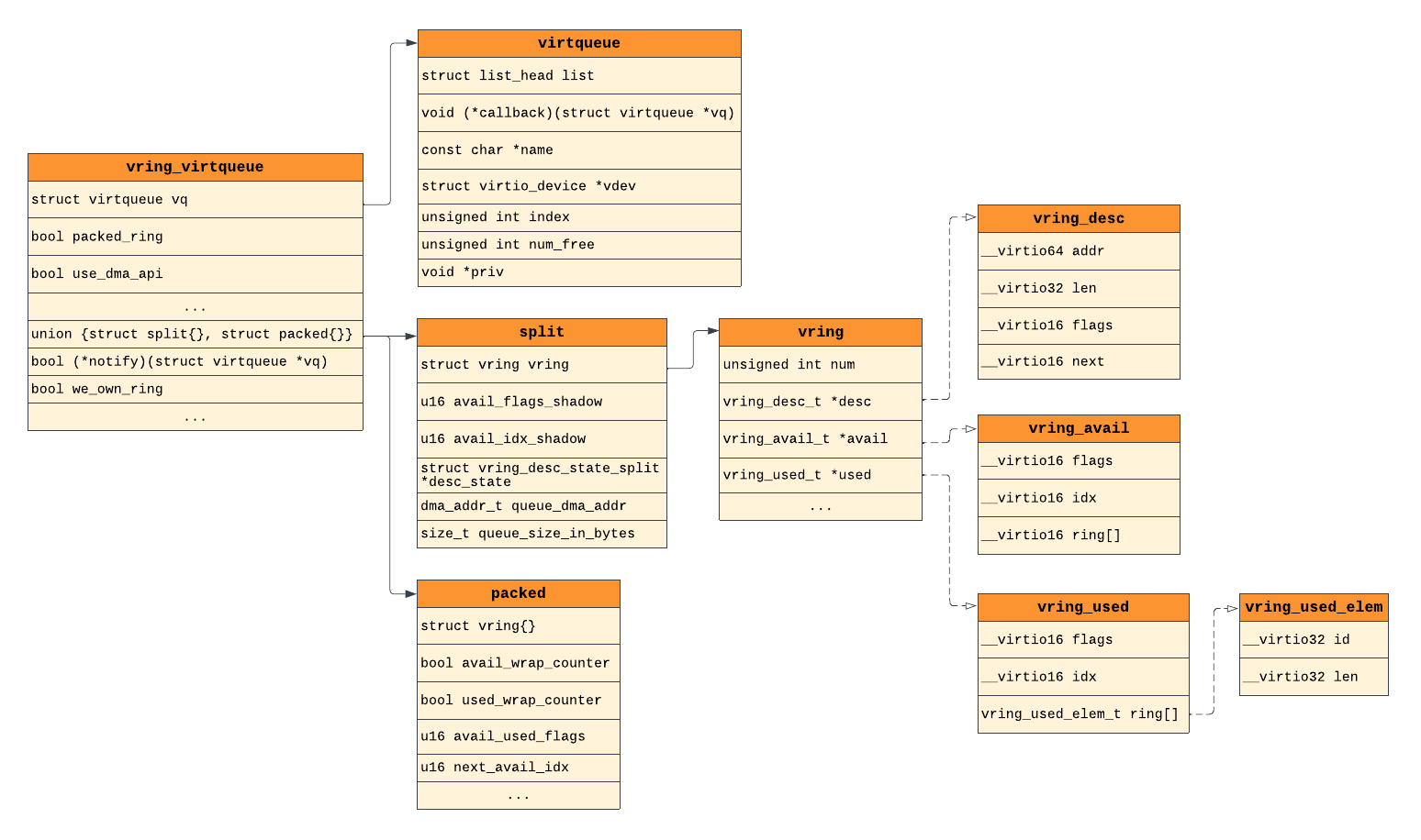
Comparing the Linux kernel’s VirtIO framework to Qemu’s in figure 3, we can clearly see the differences in their organization. However, we can also see similarities in their VRing structures (desc, avail, used), thanks to the VirtIO spec.
For now it’s not important to understand how each struct’s field contributes to VirtQueue and VRing operations. The takeaway here is to know that VirtQueues and VRings are two different data structures and that a VirtQueue’s organization will vary depending on the operating system and whether we’re talking about userland or kernel VirtIO framework.
VRings:
As we just mentioned, VRings are the main feature of VirtQueues and are the core data structures that hold the actual data being transferred. The reason they’re referred to as “rings” is because it’s essentially an array that wraps back around to the beginning of itself once the last entry was written to. These VRings are now starting to be referred to as “areas”, but since Qemu still uses the VRing term in its source code we’ll stick with that name here.
Each VirtQueue can have up to, and usually does, three types of VRings (or areas):
- Descriptor ring (descriptor area)
- Available ring (driver area)
- Used ring (device area)
Descriptor Ring (Descriptor Area):
The descriptor ring (or descriptor table, descriptor area) is essentially a circular array of descriptors, where a descriptor is a data structure that describes a data buffer. A descriptor holds the following info about its data buffer:
addr: guest-physical addresslen: length of the data bufferflags: flags (NEXT,WRITE,INDIRECT)next: index (in desc. ring) of next chained descriptor
Flags inform the device or driver (a) is there more related data in the next descriptor (NEXT), (b) is this buffer write-only (device-writable) (WRITE), and (c) does the buffer contain an indirect descriptor table (INDIRECT)? We won’t talk about indirect descriptor tables here for the sake of simplicity.
With regards to the NEXT flag, this is set when data in the current descriptor’s buffer continues into the “next” descriptor’s buffer. When one or more descriptors are linked together in this way, this is known as “descriptor chaining”. The next field refers to the index (in the descriptor ring) of the next chained descriptor. One thing worth noting about descriptor chains is that they can consist of both write-only and read-only descriptors.
Lastly, only the driver can add (write) descriptors to the descriptor ring and a device can only write to a device-writable buffer if the descriptor’s flag says the buffer is writable. A buffer can either be write-only or read-only, but never both.
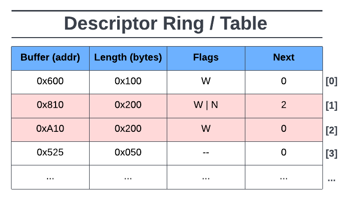
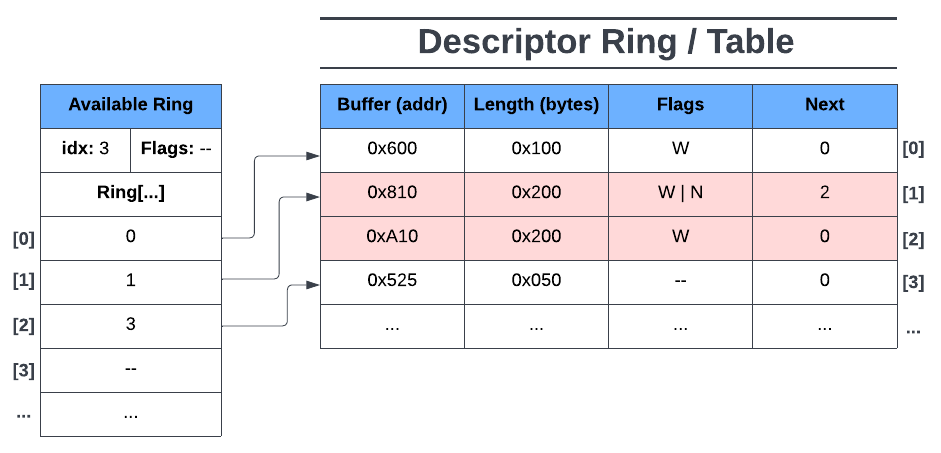
In figure 5 above we can see a descriptor ring with four descriptor entries, two of which are chained together. The first descriptor entry at index [0] tells us that the data buffer is at the GPA (guest-physical address) of 0x600, it’s data buffer is 0x100 bytes in length, and it’s flagged as device-writable (W). We know this entry isn’t the head of a descriptor chain because of no next (N) flag and the next field is set to 0.
The second descriptor entry ([1]) tells us that its data buffer is at GPA 0x810, with a data buffer length of 0x200 bytes, and flagged as device-writable and next. We know this descriptor is the head of a descriptor chain due to the next flag being raised. The next field tells us that the next descriptor in this chain is at descriptor ring index [2].
The third descriptor entry’s ([2]) data buffer continues at GPA 0xA10 for another 0x200 bytes, and the buffer is also device-writable. The descriptor chain ends here as there isn’t a next flag raised.
Finally, the fourth descriptor entry ([3]) tells us that its data buffer is at GPA 0x525, with a data buffer length of 0x50 bytes, and has no flags (device read-only, no descriptor chain).
Note that in the descriptor ring, a buffer’s GPA and length must not overlap another entry’s memory range and that the GPA to the start of the next buffer doesn’t necessarily have to be higher than the previous one (e.g. descriptor entry [3]).
Available Ring (Driver Area):
The available ring (or avail ring, driver area) is a circular array of references to available descriptors in the descriptor ring. In other words, each entry in the available ring points to a descriptor (or the head of a descriptor chain) in the descriptor ring.
Including the available ring array, the available ring also has the following fields:
flags: configuration flagsidx: index of the next available avail ring entryring[]: the actual available ring array
The flags field represents the configuration of the available ring and some of its operations. The index field represents the next available entry in the available ring where the driver would put the next reference to a descriptor (or head of a descriptor chain). Lastly, the ring field represents the actual available ring array where descriptor ring references are stored by the driver.
Only the driver may configure and add an entry to the available ring while the corresponding device can only read from it. Initially, before the driver adds its first entry to the available ring, the available ring, with no flags, would look something like Figure 6 below:
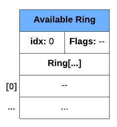
In figure 6 we can see an available ring with no entries and no flags set. The index (idx) is 0 since the next available entry of the available ring’s array is ring[0].
Now, using figure 5 as our descriptor ring, let’s say the driver adds (or makes available) the first descriptor entry on the descriptor ring. The available ring would then look like figure 7 below:
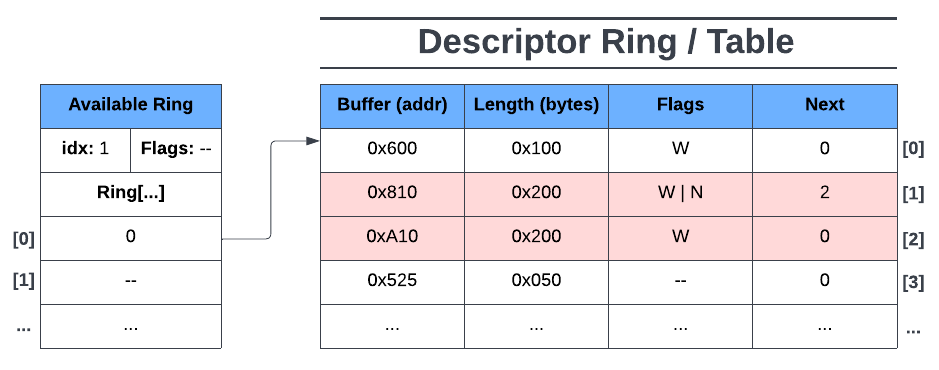
Here we can see that the driver made the first descriptor entry available to the device by adding the index of the descriptor table to the first available entry in the available ring (ring[0]). We can also see that idx is now 1 as ring[1] is now the next available entry on the ring. In this state, only the first entry of the descriptor ring is readable by the device and has no access to the other descriptors.
Now lets say the driver adds the next descriptor entry to its available ring. Note that the next descriptor entry is the head of a descriptor chain. The available ring would then look like figure 8:
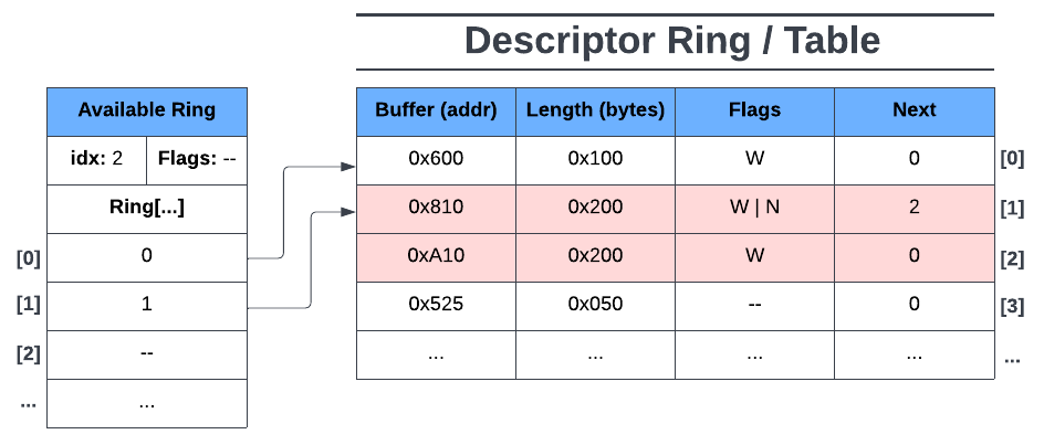
Here we see the driver made the second and third descriptor entries available (chained descriptors). Now ring[1] points to the head of a descriptor chain, giving the device access to all of its chained descriptors. idx is set to 2 since ring[2] is now the next available entry on the available ring.
Finally, say the driver adds the next descriptor entry to the available ring. Now the available ring looks like figure 9 below:
Here we see the driver has made the fourth descriptor entry available to the device by adding its descriptor ring’s index to the next available entry on the available ring (ring[2]). Note that in ring[2] the descriptor ring’s index is 3. This was because ring[1] includes both descriptor ring indices 1 & 2 (chained). Lastly, the available ring’s idx is now 3, since the next available entry on the available ring is ring[3].
In summary, the driver is the only one who can add descriptor entries and available ring entries to the descriptor and available rings respectively. The device, however, cannot access this data until the driver adds the corresponding descriptor ring index into the available ring.
Used Ring (Device Area):
The used ring (or device area) is similar to the available ring except that it’s a circular array of references to used descriptor entries on the descriptor ring (i.e. the device wrote to or read a descriptor’s data buffer).
The following fields make up the used ring:
flags: configuration flagsidx: index of next available used ring entryring[]: the actual used ring array (of data pair structs)id: index of descriptor ring this element refers to
len: length of data written to descriptor(s) buffer(s)
Unlike the available ring array, each entry on the used ring are pairs of data (represented as a “used element” structure) that describe (1) the index (id) of a descriptor (or head of chained descriptors) in the descriptor ring that references used (read or written to) buffer(s) and (2) the total written length (len) into a descriptor’s buffer (or the total written length of all buffers in a descriptor chain).
Similar to the available ring, the used ring also makes use of the flags and idx fields. The index field is the same as the index field for the available ring except, for the used ring, this represents the next available entry in the used ring array.
Opposite to the available ring, only the device can configure and add entries to the used ring while the corresponding driver can only read from it.
Initially, before the device starts processing data from the available ring, the used ring (with no flags) would look like figure 10 below:
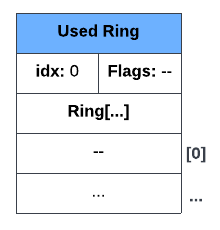
Here we see an empty used ring with the next available used ring index (idx) set to 0 for ring[0], nothing too special here.
Now let’s see what happens when the device finishes processing the first available ring entry and adds an entry to its used ring (using figure 10 above). Recall that the first descriptor’s data buffer was marked as device-writable, so let’s say the device wrote 0x50 bytes to the descrptor’s device-writable buffer. The resulting used ring would look like the following:

In figure 11 above we can see the used ring entry’s data pair present: 0 | 0x50. 0 (id) represents the index on the descriptor ring where the device used (in this case, wrote to) the descriptor’s data buffer and 0x50 (len) is the total number of bytes written into the descriptor’s data buffer. Lastly, the used ring’s idx was set to 1 as that is now the next available entry on the used ring.
Let’s see how the next entry on the used ring looks after the device processes the second available ring entry. Recall that the second entry of the available ring points to a descriptor chain where both descriptors are device-writable. Let’s also say that the device wrote 0x200 bytes in the first descriptor’s data buffer and 0x150 in the second descriptor’s data buffer. The resulting used ring is shown below in figure 12:
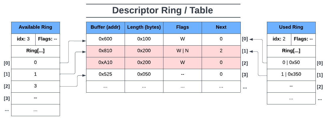
Here we can see how a used ring entry would look like given a descriptor chain with multiple data buffers written to. The index of a used ring entry always points either to a single descriptor or a head of a descriptor chain. In this case used ring[1] points to the head of the descriptor chain at descriptor ring index 1.
The length in the used ring entry for a descriptor chain represents the total number of bytes written into each of the chained descriptor’s data buffers. Since the device wrote 0x200 bytes into the first chained descriptor’s data buffer and 0x150 bytes into the second chained descriptor’s data buffer, this would mean that the total written length across all of the chained descriptors would be 0x350.
Finally, let’s have the device process the third entry of the available ring and add its corresponding used ring entry. Note that the third entry of the available ring points to a descriptor with no flags, meaning it’s a single descriptor and its data buffer is read-only for the device. The used ring would look like figure 13 below:
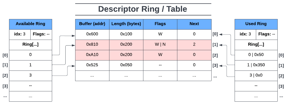
Here we can see how a used ring entry would look like given a single read-only descriptor. What’s worth noting here is the length 0x0 in the used ring entry’s data pair. It has a value of zero here simply because nothing was written to this buffer (being read-only for the device). Lastly, as expected, the index in the used ring entry is 3 here since index 2 of the descriptor ring was part of a descriptor chain.
VRings Summary:
In this section we covered the descriptor, available, and used rings with an example descriptor ring data set. It should be emphasized here that the examples above are very simple and don’t show the role of notifications nor does it show other VRing configurations (e.g. indirect descriptors, used buffer notification suppression, packed VirtQueues, etc.). However, it does show the general purpose behind each of the three rings and how they work together with devices and drivers.
In summary, VRings are a way in which data is exchanged between a guest and its host. In the above examples we saw how the VirtIO driver makes requests to the device in the form of descriptor references on the available ring, the device accessing the requests via the available ring, and the device making the processed request available to the driver via the used ring.
In the next section we’ll look at an example VirtIO device in Qemu to see how it uses its VirtQueues and how its VirtQueues use its VRings.
Honorable Mention: VHost
In this article we’re not going to go in depth about VHost but anyone starting to learn about VirtIO has likely already seen the “VHost” term being mentioned. Thus it’s worth briefly describing here for those who’re still unfamiliar with it.
Unlike VirtIO drivers & devices, whose data plane exists in the Qemu process, VHost can offload the data plane to either another host user process (VHost-User) or to the host’s kernel (VHost, as a kernel module). The motivation behind doing this is performance. That is, in a pure VirtIO solution like figure 2, everytime the driver requests the host to do some processing on its physical hardware, a context switch occurs. These context switches are expensive operations that add a significant amount of latency between requests. By offloading the data plane to another host user process or to its kernel, we essentially bypass the Qemu process, thus increasing performance by reducing latency.
However, while it does increase performance it also adds a level of security concern given the fact that the data path is now going directly into the host’s kernel.
Figure 14 below shows the general layout of an example VHost (VHost-SCSI):
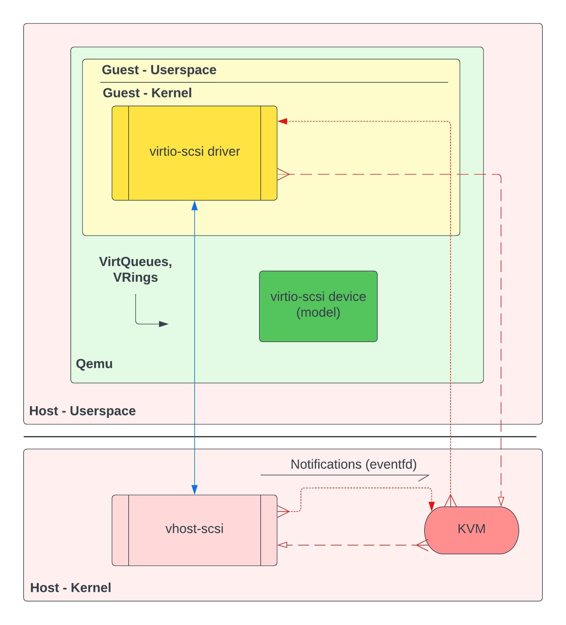
If we compare the general framework of VHost in figure 14 to the pure VirtIO framework in figure 2, we see a few key differences:
- The transport layer (or data plane) is now from the guest’s kernel to the host’s kernel
- A VirtIO device model is present, but its capabilities are reduced to handling control plane tasks
- A VHost-SCSI kernel module exists in the host’s kernel
This is only a generalization of the organization between a VHost configuration and a pure VirtIO configuration. There’s more that can be said about VHost & VHost-User and the capabilities they bring. However, for this article, we will focus only on a pure VirtIO implementation similar to figure 2.
VirtIO in Qemu
In this section we’re going to take a look at an example VirtIO device in Qemu and see how one of its VirtQueues works. The goal here is to see not only how a VirtIO device roughly works, but to also see the role of VirtQueues and VRings in a standard VirtIO device. For our example device, let’s take a look at virtio-SCSI using a split VirtQueue configuration and the VIRTIO_VRING_F_EVENT_IDX feature bit negotiated.
Virtio-SCSI:
The virtio-SCSI device is used to group virtual logical units (e.g. hard disk drives) together and enables communication to them via the SCSI protocol. For our example, let’s assume we’re only using the device to connect to a hard disk drive. Qemu invocation parameters for this device (using a HDD) might include something like below:
-device virtio-scsi-pci
-device scsi-hd,drive=hd0,bootindex=0
-drive file=/home/qemu-imgs/test.img,if=none,id=hd0
In the Qemu source code, if we take a look at hw/scsi/virtio-scsi.c, we can see various functions related to the device’s operations. Let’s take a look at how this device is set up, specifically its VirtQueues.
In Qemu, the term “realize” is used to represent the initial setup and configuration of a VirtIO device (and “unrealize” to tear down a device). In the function virtio_scsi_common_realize(), we can see three different types of VirtQueues being set up for the virtio-SCSI device:
// In hw/scsi/virtio-scsi.c
void virtio_scsi_common_realize(DeviceState *dev,
                                VirtIOHandleOutput ctrl,
                                VirtIOHandleOutput evt,
                                VirtIOHandleOutput cmd,
                                Error **errp)
{
    ...
    s->ctrl_vq = virtio_add_queue(vdev, s->conf.virtqueue_size, ctrl);
    s->event_vq = virtio_add_queue(vdev, s->conf.virtqueue_size, evt);
    for (i = 0; i < s->conf.num_queues; i++) {
        s->cmd_vqs[i] = virtio_add_queue(vdev, s->conf.virtqueue_size, cmd);
    }
}
Most VirtIO devices will have multiple VirtQueues, with each VirtQueue having their own unique functionality. In the virtio-SCSI case, we have a control VirtQueue (ctrl_vq), an event VirtQueue (event_vq), and one or more command (or request) VirtQueues (cmd_vqs).
The control VirtQueue is used for task management functions (TMFs) such as starting up, shutting down, resetting, etc. the virtio-SCSI device. It is also used for subscribing to and querying asynchronous notifications.
The event VirtQueue is used for reporting information (events) from the host on logical units attached to virtio-SCSI. These events include transport events (e.g device resets, rescans, hot-plug, hot-unplug, etc.), asynchronous notifications, and logical unit number (LUN) parameter changes.
Lastly, the command or request VirtQueues are used for typical SCSI transport commands (e.g. reading and writing to and from files). In this section we’ll focus on the operations of the command VirtQueueg as it’s more interesting and used more compared to the other two.
The Command VirtQueue:
The command (or request) VirtQueue is the VirtQueue we’ll be focusing on in this section. It is the VirtQueue that is used to transfer information regarding typical SCSI transport commands like reading and writing to files. Virtio-SCSI can have one or more of these command VirtQueues.
As mentioned before, VirtQueues structures in Qemu have a callback function field for handling output called VirtIOHandleOutput handle_output. In the case of virtio-SCSI’s command VirtQueue, this callback function field will point to virtio-SCSI’s command VirtQueue handler function virtio_scsi_handle_cmd():
// In hw/scsi/virtio-scsi.c
static void virtio_scsi_device_realize(DeviceState *dev,
                                       Error **errp)
{
    VirtIODevice *vdev = VIRTIO_DEVICE(dev);
    VirtIOSCSI *s = VIRTIO_SCSI(dev);
    Error *err = NULL;

    virtio_scsi_common_realize(dev,
                               virtio_scsi_handle_ctrl,
                               virtio_scsi_handle_event,
                               virtio_scsi_handle_cmd, <----*
                               &err);
    ...
}

// In hw/virtio/virtio.c
VirtQueue *virtio_add_queue(VirtIODevice *vdev, int queue_size,
                            VirtIOHandleOutput handle_output)
{
    ...

    vdev->vq[i].vring.num = queue_size;
    vdev->vq[i].vring.num_default = queue_size;
    vdev->vq[i].vring.align = VIRTIO_PCI_VRING_ALIGN;
    vdev->vq[i].handle_output = handle_output; <----*
    vdev->vq[i].used_elems = g_malloc0(sizeof(VirtQueueElement)
                                       * queue_size);
    return &vdev->vq[i];
}
The way this output handler function of a VirtQueue is called depends on the VirtIO device and that VirtQueue’s role for the device. In the case of virtio-SCSI’s command VirtQueue, it’s output handler function is called when a notification is sent from the virtio-SCSI driver to Qemu, telling Qemu to notify its device counterpart that there’s SCSI command data ready for processing on it’s available VRing.
Recall figure 2 and that we’re looking at Qemu’s source code, more specifically VirtIO device code. Also recall from the VRings section earlier that VirtIO devices don’t start getting involved in VRing operations until its corresponding VirtIO driver has (1) added new descriptors to the descriptor ring, (2) made those descriptors available to the device by adding descriptor reference entries to the available ring, and (3) notified its device that the available ring is ready for processing.
In other words, when execution reaches the virtio_scsi_handle_cmd() function, it means that the virtio-SCSI device has received a notification from its driver and is beginning to start processing data from its command VirtQueue’s available ring. You can think of the current state of the available and descriptor rings being similar to figure 9.
The virtio_scsi_handle_cmd() function is more or less a wrapper for the virtio_scsi_handle_cmd_vq() function below:
// In hw/scsi/virtio-scsi.c
bool virtio_scsi_handle_cmd_vq(VirtIOSCSI *s, VirtQueue *vq)
{
    VirtIOSCSIReq *req, *next;
    int ret = 0;
    bool suppress_notifications =
            virtio_queue_get_notification(vq);
    bool progress = false;

    QTAILQ_HEAD(, VirtIOSCSIReq) reqs =
            QTAILQ_HEAD_INITIALIZER(reqs);

    do {
        if (suppress_notifications) {
            virtio_queue_set_notification(vq, 0);
        }
        while ((req = virtio_scsi_pop_req(s, vq))) {
            progress = true;
            ret = virtio_scsi_handle_cmd_req_prepare(s, req);
            if (!ret) {
                QTAILQ_INSERT_TAIL(&reqs, req, next);
            } else if (ret == -EINVAL) {
                /* The device is broken and shouldn't
                   process any request */
                while (!QTAILQ_EMPTY(&reqs)) {
                    ...
                }
            }
        }
        if (suppress_notifications) {
            virtio_queue_set_notification(vq, 1);
        }
    } while (ret != -EINVAL && !virtio_queue_empty(vq));

    QTAILQ_FOREACH_SAFE(req, &reqs, next, next) {
        virtio_scsi_handle_cmd_req_submit(s, req);
    }
    return progress;
}
This function here tells us how virtio-SCSI’s command VirtQueue will handle and process the data on its available ring.
For the following scenario, recall that the VIRTIO_VRING_F_EVENT_IDX feature bit was negotiated. For the device, this means that it will only notify its driver if the idx in the used ring is equal to the idx in the available ring.
In other words, if the driver makes available 20 entries on the available ring from indices 0 to 19, the available ring’s idx will be 20 after adding the last descriptor reference to available ring[19]. After the device processes the last available ring entry and puts its corresponding used ring entry on used ring[19], the used ring’s idx will also be 20. When this happens, almost immediately after adding the last used ring entry, the device must then notify its driver.
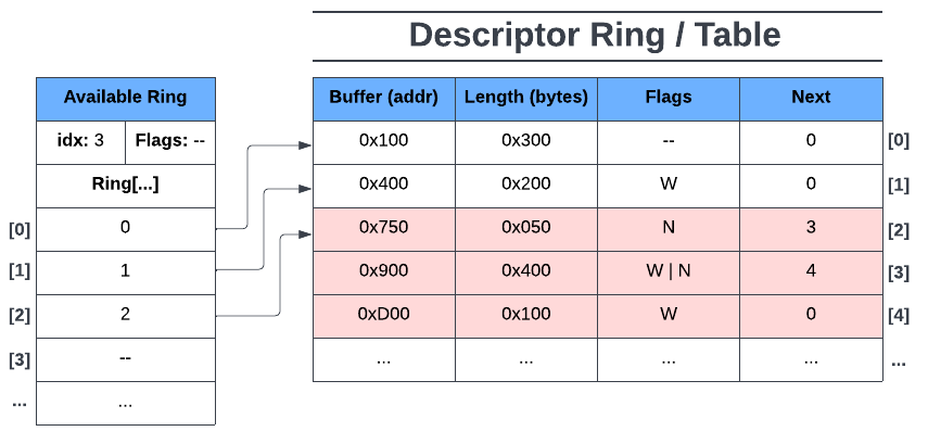
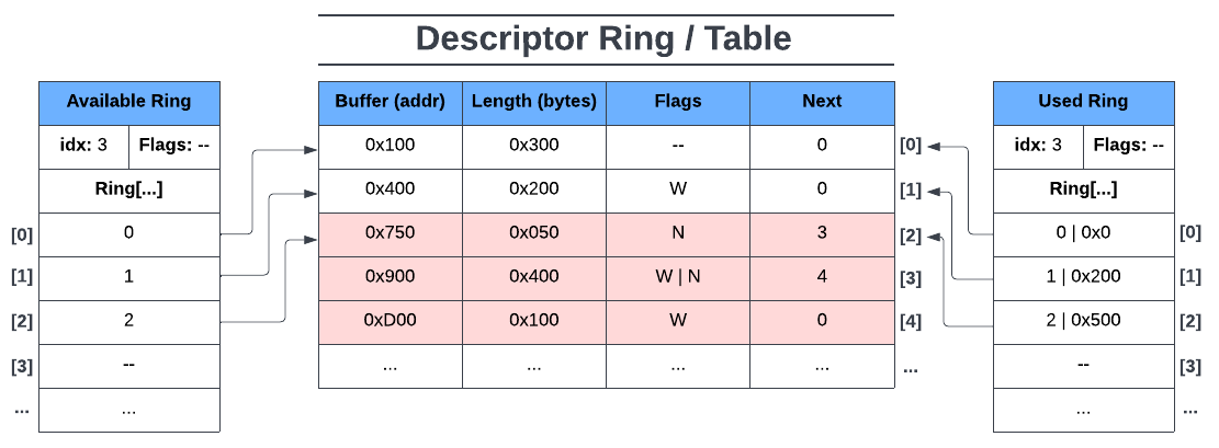
Before execution begins in virtio_scsi_handle_cmd_vq(), let’s say its command VirtQueue’s descriptor and available ring look like figure 15 below:
Looking back at virtio_scsi_handle_cmd_vq(), let’s walk through this function to see how the virtio-SCSI device handles the data that it’s just been notified of.
First off, at the beginning of the function, a queue data structure of virtio-SCSI requests (VirtIOSCSIReq), called reqs, is initialized :
QTAILQ_HEAD(, VirtIOSCSIReq) reqs = QTAILQ_HEAD_INITIALIZER(reqs);
For the virtio-SCSI’s command VirtQueue, each entry on its available ring is made into a VirtIOSCSIReq object that is appended at the end of the reqs queue. We can see this is the case looking at the do-while loop that comes right after it:
// virtio_scsi_handle_cmd_vq
do {
    /* Turn off notifications if we're suppressing them */
    if (suppress_notifications) {
        virtio_queue_set_notification(vq, 0);
    }
    while ((req = virtio_scsi_pop_req(s, vq))) {
        progress = true;
        ret = virtio_scsi_handle_cmd_req_prepare(s, req);
        if (!ret) {
            QTAILQ_INSERT_TAIL(&reqs, req, next);
        } else if (ret == -EINVAL) {
        /* The device is broken and shouldn't
           process any request */
            ...
        }
    }
    /* Turn on notifications if we've been suppressing them */
    if (suppress_notifications) {
        virtio_queue_set_notification(vq, 1);
    }
} while (ret != -EINVAL && !virtio_queue_empty(vq));
Before we start reading the available ring, we first suppress any notifications being sent to the driver by the device (VIRTIO_VRING_F_EVENT_IDX). Then we enter the second while loop while ((req = virtio_scsi_pop_req(s, vq))). In this while loop, we’re going through the available ring and for each entry we put its data into a VirtIOSCSIReq object. Each VirtIOSCSIReq object is then appended to the end of the reqs queue.
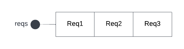
By the end of the while loop we would have something like figure 16 below, where Req1 refers to VirtIOSCSIReq object created from reading available ring entry ring[0], Req2 is the VirtIOSCSIReq object from reading available ring entry ring[1], and similarly Req3 from the available ring entry ring[2]:
After we’ve read all we can from the available ring we then renable notifications so that the device can notify the driver of used data once the device has processed the requests and put them on the used ring. Note that this only enables notifications, not send them. In our scenario (with VIRTIO_VRING_F_EVENT_IDX), this just sets us up to notify our device once we’ve put all of our processed requests’ data onto the used ring.
Before we actually go and submit our requests, you’ll notice that we’re still in the do-while loop that terminates if the device broke or if we haven’t read all the data from the available ring. This is here in case more data was added to the available ring right after we read the last entry from it.
Now that the device has read all it can from the available ring and converted each entry into its own VirtIOSCSIReq object, we then loop through the reqs queue and submit each request individually for processing by the actual physical SCSI device:
QTAILQ_FOREACH_SAFE(req, &reqs, next, next) {
    virtio_scsi_handle_cmd_req_submit(s, req);
}
Once a request has been fulfilled by the host’s SCSI device, execution then goes to virtio_scsi_command_complete(), then virtio_scsi_complete_cmd_req(), and then finally virtio_scsi_complete_req(). The more interesting of the three functions is virtio_scsi_complete_req(), as this is the function where the device puts used data onto the used ring.
Let’s take a look at it:
// In hw/scsi/virtio-scsi.c
static void virtio_scsi_complete_req(VirtIOSCSIReq *req)
{
    VirtIOSCSI *s = req->dev;
    VirtQueue *vq = req->vq;
    VirtIODevice *vdev = VIRTIO_DEVICE(s);

    qemu_iovec_from_buf(&req->resp_iov, 0, &req->resp,
                        req->resp_size);
    /* Push used request data onto used ring */
    virtqueue_push(vq, &req->elem,
                   req->qsgl.size + req->resp_iov.size);
    /* Determine if we need to notify the driver */
    if (s->dataplane_started && !s->dataplane_fenced) {
        virtio_notify_irqfd(vdev, vq);
    } else {
        virtio_notify(vdev, vq);
    }

    if (req->sreq) {
        req->sreq->hba_private = NULL;
        scsi_req_unref(req->sreq);
    }
    virtio_scsi_free_req(req);
}
To complete a request, the virtio-SCSI device must make the processed data accessible to the driver by putting it on the used ring (virtqueue_push()). Remember, the actual data has already been written to a descriptor’s buffer by this point (or to multiple buffers from chained, writable descriptors). All we’re doing now is telling the driver where to look in the descriptor ring and how much we wrote to its data buffer, if anything.
After adding an entry to the used ring for Req1, our command VirtQueue’s VRings would look like figure 17 below:
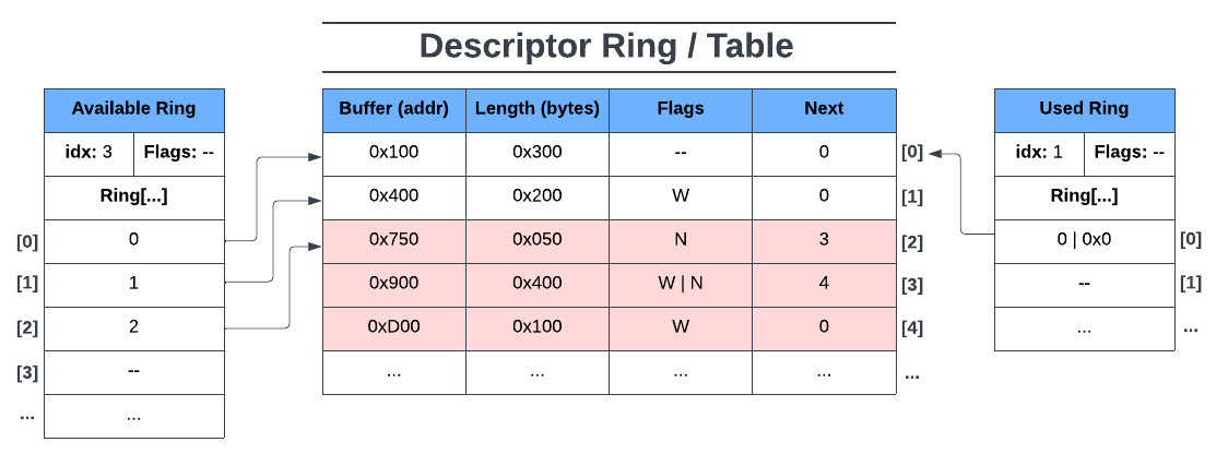
The first request referred to a device read-only buffer so the descriptor index is 0 and the written length is 0. idx is also incremented to 1. After virtqueue_push() we then check to see if we should notify the driver.
Recall that our device is using the VIRTIO_VRING_F_EVENT_IDX feature. In our example, the device would notify the driver once our used ring idx is 3. Thus, for this request, no notification is sent to the driver.
The next two requests refer to device-writable buffers. For consistency, let’s say the written length of Req2 is 0x200 and for Req3 it’s 0x500. Immediately after returning from virtqueue_push() for Req3, the used ring would look like figure 18 below:
Now the device will notify the driver of the contents of the used ring since the condition for the device’s feature VIRTIO_VRING_F_EVENT_IDX was met. That is, the used ring’s idx is equal to the available ring’s idx. Once the driver has been notified, the driver goes into the used ring to find the processed data on the descriptor ring and does whatever it wanted to with the data.
After notifying the driver and doing some cleanup work, the job of the virtio-SCSI device has been completed and goes back to waiting for the driver to notify it of new data to process on its available ring.
VirtIO Summary
In this article we went over what VirtIO is, why we should care, its alternatives (e.g. emulation), and key concepts such as devices & drivers, VirtQueues, and VRings. We then looked at a standard VirtIO device (in Qemu) and followed the execution of one of its VirtQueues to extrapolate the role of VirtQueues and VRings in a VirtIO device.
It should be noted that this article barely scratches the surface of VirtIO, as we’ve only covered the bare basics and used simple examples. In our examples we only assumed a split VirtQueue configuration and only used the VIRTIO_RING_F_EVENT_IDX feature bit. For example, we didn’t go into detail about notifications, VirtIO driver-side code (in kernel), or other features that modify the operations of VirtQueues and its VRings (e.g. “packed” VirtQueues, indirect descriptors, in-order descriptor use, SR-IOV, etc.).
Regardless, this article should create a solid working knowledge of VirtIO such that learning about other VirtIO devices or concepts is much easier to pick up.
References
- https://www.linux-kvm.org/images/archive/f/f5/20110823142849!2011-forum-virtio-scsi.pdf
- https://projectacrn.github.io/latest/developer-guides/hld/hld-virtio-devices.html#
- https://insujang.github.io/2021-03-10/virtio-and-vhost-architecture-part-1/
- https://www.cs.cmu.edu/~412/lectures/Virtio_2015-10-14.pdf
- https://www.redhat.com/en/blog/virtio-devices-and-drivers-overview-headjack-and-phone
- https://www.redhat.com/en/blog/virtqueues-and-virtio-ring-how-data-travels
- https://www.redhat.com/en/blog/introduction-virtio-networking-and-vhost-net
- https://www.redhat.com/en/blog/journey-vhost-users-realm
- https://www.dell.com/en-us/blog/emulation-or-virtualization-what-s-the-difference/
- https://www.hitechnectar.com/blogs/virtualization-emulation/
- https://developer.ibm.com/articles/l-virtio/
- https://www.linaro.org/blog/virtio-work/
- https://docs.oasis-open.org/virtio/virtio/v1.1/csprd01/virtio-v1.1-csprd01.html
- https://developpaper.com/original-kvm-qemu-analysis-of-linux-virtualization-11-virtqueue/