Oracle Container Engine for Kubernetes (OKE) is a managed service that runs Kubernetes on Oracle Cloud Infrastructure (OCI) without needing to install, operate, and maintain your own Kubernetes control plane or nodes. OKE supports native virtual cloud networks (VCNs) with the first release. This container network interface (CNI) plugin assigns a private IPv4 address from your VCN to each pod. The VCN CNI allows Kubernetes pods to utilize raw OCI network performance and integrations with other OCI services.
Today, we’re excited to introduce OCI VCN CNI 2.0.0, a major update of networking implementation for Oracle Kubernetes Engine. We have made significant enhancements to the networking implemented by OCI VCN CNI. With this enhancement, you get the following benefits:
-
Service mesh products, such as OCI Service Mesh, Istio, and Linkerd, are supported when using the OCI VCN-native pod networking CNI plugin for pod networking.
-
Improvements in network performance
The new networking enhancements in OCI VCN CNI are available in Kubernetes versions 1.26 and above. Both the Kubernetes control plane and worker nodes need to be on 1.26 and higher to get the VCN 2.0.0 benefits. For more information, see the the OCI VCN CNI 2.0.0 release notes.
In this blog, we see how OCI VCN CNI 2.0.0 enables pod-to-pod communication using VCN IP addresses, whether the pod is deployed on the same worker node, across worker nodes in the cluster, or with network policy plugins like Calico and a service mesh.
Understanding the CNI flow
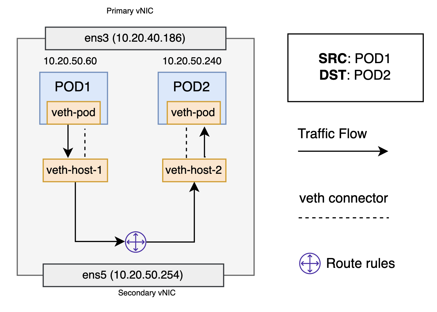
From the pod’s perspective, it exists in its own network namespace that needs to communicate with other network namespaces on the same node. You can connect namespaces using a Linux virtual ethernet device or veth pair, consisting of two virtual interfaces that can spread over multiple namespaces. The new CNI only creates a veth pair device with one end in the pod namespace and the other in the host namespace. All communication (Pod to host, pod to pod, pod to external service) traffic flows through this veth device into the host namespace, where it will be appropriately routed towards its destination. Each veth pair works like a patch cable, connecting the two sides and allowing traffic to flow between them.
Pod-to-pod, same worker node
Given the network namespaces that isolate each pod to their own networking stack, virtual ethernet devices that connect each namespace to the host namespace, and a routing rule in the host namespace that connects namespaces together, pods can send traffic to each other within the same worker node. Every pod has a virtual ethernet device or veth pair and route rules associated with it. The VCN never seen the traffic during this flow.
Pod-to-pod, across worker nodes
Every worker node in the cluster is assigned a random secondary IP address from the pod subnet chosen by the user. These secondary IP addresses are available to pods running on that node. When the traffic destined for the IP address reaches the node, the node forwards the traffic to the correct pod. The destination pod (10.20.50.154) is on a different node from the source pod (10.20.50.60). The packet begins by being sent through pod 1’s virtual ethernet device, which is paired with the virtual ethernet device in the host namespace. Ultimately, the packet ends up at the host namespace’s routing table. The worker nodes local routing forwards the packet to the secondary virtual network interface card (VNIC), ens5.
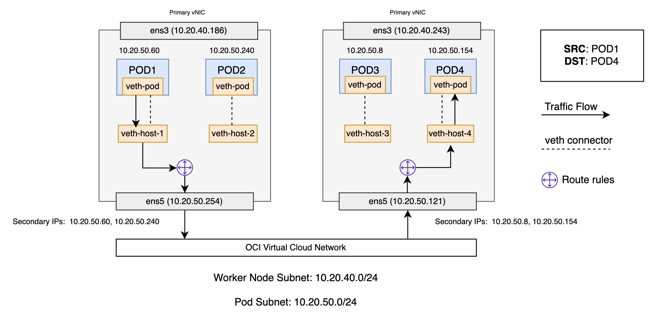
Now, the route leaves the source worker node and enters the VCN. The VCN routes the packet to the correct worker node based on the secondary IP addresses assigned to the worker node. The packet enters the host namespace of the destination worker node, where it routes through the route rules to determine the correct virtual ethernet device (veth-host-4). Finally, the route completes by flowing through the virtual ethernet device’s pair residing within pod 4’s namespace. Each worker node knows how to deliver packets to the pods running within it. When a packet reaches a destination worker node, packets flow the same way they do for routing traffic between pods on the same node.
Pod-to-service networking
When creating a new Kubernetes service, a new virtual IP, also known as a cluster IP, is created for you. Anywhere within the cluster, traffic addressed to the virtual IP is load-balanced to the set of backing pods associated with the service. In effect, Kubernetes automatically creates and maintains a distributed in-cluster load balancer that distributes traffic to a service’s associated healthy pods.
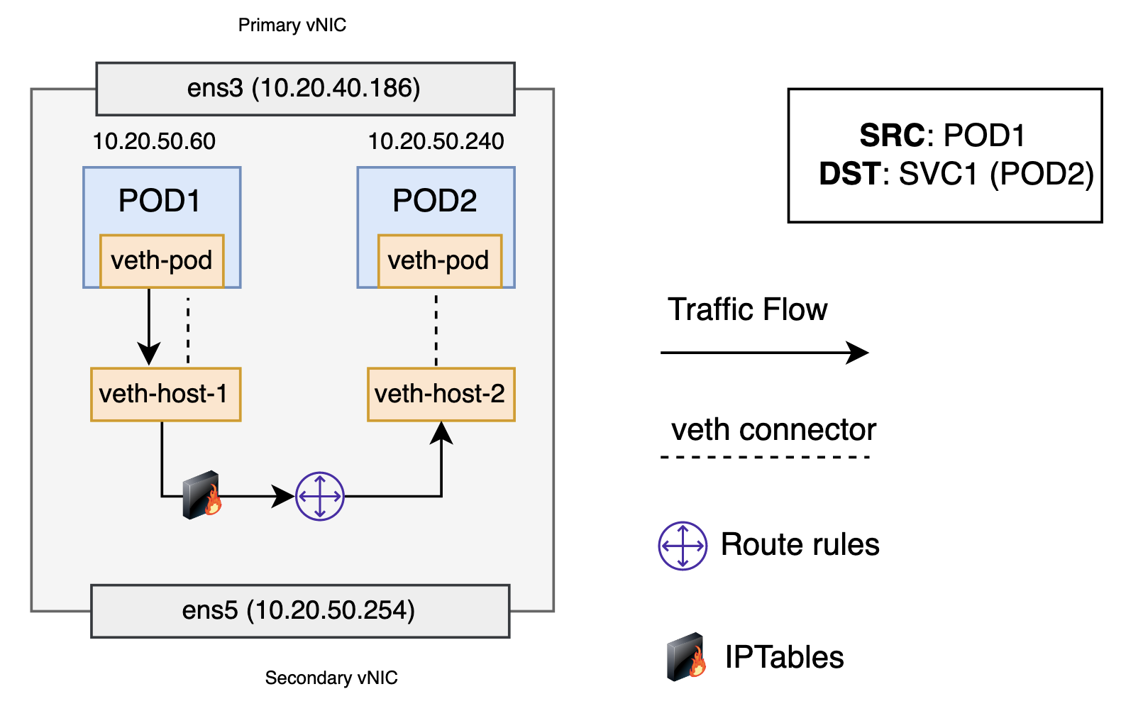
The packet first leaves the pod through the veth interface attached to the pod’s network namespace. Then it travels through the host’s virtual ethernet device. Here, something different happens. Before being accepted at the route rules, the packet is filtered through iptables. After receiving the packet, iptables uses the rules installed on the node by kube-proxy in response to service or pod events to rewrite the destination of the packet from the service IP to a specific pod IP. Iptables uses the Linux kernel’s conntrack utility to remember the pod choice so that future traffic is routed to the same pod. The packet then goes to the host route table. The packet is now destined to reach pod 2, in this example, rather than the service’s virtual IP. Traffic then flows to the pod using the pod-to-pod routing we’ve already walked through in the previous section. If the destination pod resides outside the local worker node, it redirects the traffic as explained in the section about pod-to-pod, across worker nodes.
Network policy enforcement
Network policy plugins like Calico provide a rich set of network policies with a unified syntax to protect pods. Calico uses iptables for policies and enforces the policies that apply to each pod on that specific pod’s virtual ethernet interface. Iptables rules serve as a firewall for the worker node to define the characteristics that the network traffic must meet to be forwarded to the destined pod.
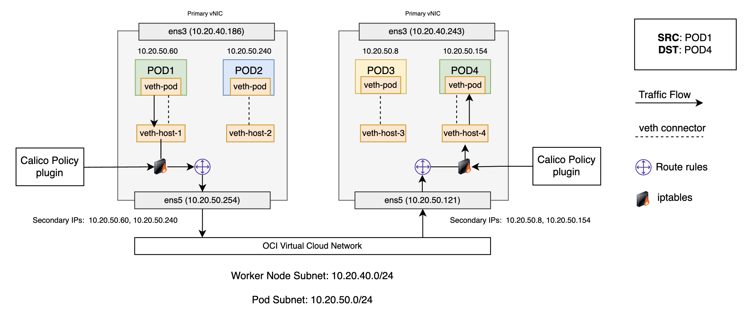
This example uses a network policy where only same color pods can talk to each other. On a Kubernetes worker node running Calico, a veth is mapped to a workload (Pod). For every workload, Calico creates hooks into various chains in the network processing path using iptables. Calico applies it to each pod on that specific pod’s virtual ethernet interface and watches them. Because traffic arrives over the virtual interface, it passes through iptables. As the packet comes in through the network interface, it goes through the standard iptables chains. A routing decision is made and, based on that, the packet gets directed to host processes or directed to a pod or to another node in the network. If no policies have been applied, packets entering the destination worker node are delivered to the workload unimpeded and returned in the same manner.
Now, let’s assume a policy is added to protect pod 4 from being accessed by any node outside the cluster. This requires blocking access to pod 4 from any worker node within the cluster. These policies are enforced by the filter table inside iptables responsible for dropping and rejecting packets. If we go over the entire traffic flow with policies applied, while traversing through the iptables and routing decisions, the traffic is dropped by Calico policies enforced in the filter chain. For details about how traffic flows with different policies applied, see Understanding the policy enforcement options with Calico.
Service mesh
The most common service mesh implementation is with the Kubernetes container orchestration platform, which uses a sidecar model. The service mesh implements the network functionality in a layer 4 sidecar proxy and then relies on traffic from and to services to be redirected to this sidecar proxy. The application container sits next to the proxy sidecar container in the same pod. Because they’re in the same pod, they share the same network namespace and IP address, which allows the containers to communicate through localhost.
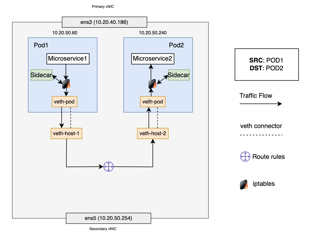
In the service mesh and Istio model, each pod has its own firewall rules (iptables) and network devices (veth pair and sidecar container). In this scenario, pod 1 wants to communicate with pod 2, and both pods are on the same worker node. Pod 1 sends a packet to its default ethernet device, veth-pod. The iptables rule in pod 1’s network namespace redirects the packet to the sidecar. After processing the packet, the sidecar recovers the original destination IP address and port and then forwards the packet to veth-pod. For pod 1, veth-pod connects to the host network namespace using veth-host-1. The route rules connect veth-host-1 to all the other virtual devices on the node. When the packet reaches the route rules, they determine that the correct next hop is veth-host-2 to reach pod 2. When the packet reaches the virtual device veth-host-2, it’s forwarded to veth-pod in pod 2’s network namespace. Eventually, the packet gets forwarded to the sidecar and finally to the application.
Next steps
In this blog, we discussed in detail VCN CNI traffic flows going east to west. To understand how the traffic flows north to south using load balancers, see Using a network load balancer for Kubernetes services. For more information about pod networking in OCI VCN CNI, see the OCI VCN CNI documentation.
We encourage you to create issues on the Oracle Cloud Infrastructure support portal and help improve this plugin.